Movable and static ring for integrated sand mill

A sand mill, an integrated technology, applied in the field of dynamic and static rings, can solve the problems of cumbersome grinding process, uneven distribution of grinding media, poor particle size distribution, etc., and achieve the effect of improving grinding quality and improving uneven distribution of grinding media

Pending Publication Date: 2021-02-09
CHANGZHOU LONGXIN MACHINERY
View PDF0 Cites 0 Cited by
  • Summary
  • Abstract
  • Description
  • Claims
  • Application Information

AI Technical Summary

Problems solved by technology

[0002] The sand mill is used for fine grinding of materials, which can realize continuous processing and continuous discharge of materials. Since traditional sand mills basically use wet grinding, the ground materials need to be dried, resulting in a more cumbersome grinding process.
Therefore, there is an integrated sand mill for dry grinding. The material is ground through the coarse grinding chamber and the fine grinding chamber in the body. In the grinding chamber of the traditional sand mill, grinding discs arranged in a certain order are installed on the main shaft. , with the grinding medium to grind the material, but this conventional grinding disc is likely to cause uneven distribution of the grinding medium and poor particle size distribution after grinding

Method used


Image

  • Movable and static ring for integrated sand mill
  • Movable and static ring for integrated sand mill

Examples


Embodiment Construction

[0014] The present invention is described in further detail now in conjunction with accompanying drawing. These drawings are all simplified schematic diagrams, which only illustrate the basic structure of the present invention in a schematic manner, so they only show the configurations related to the present invention.

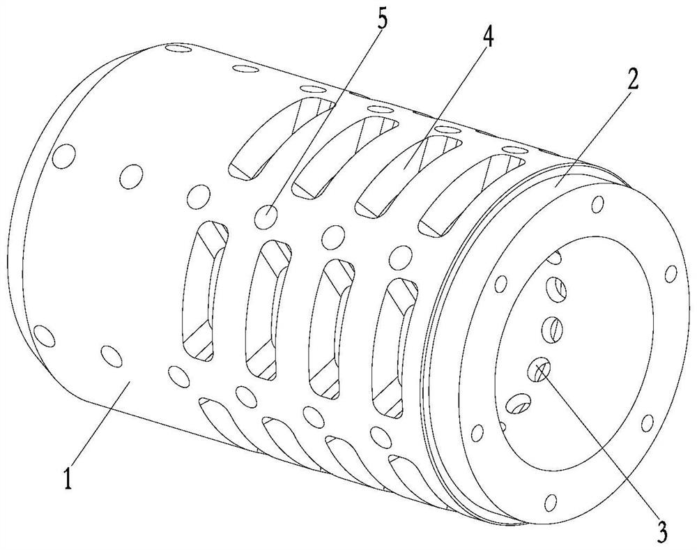
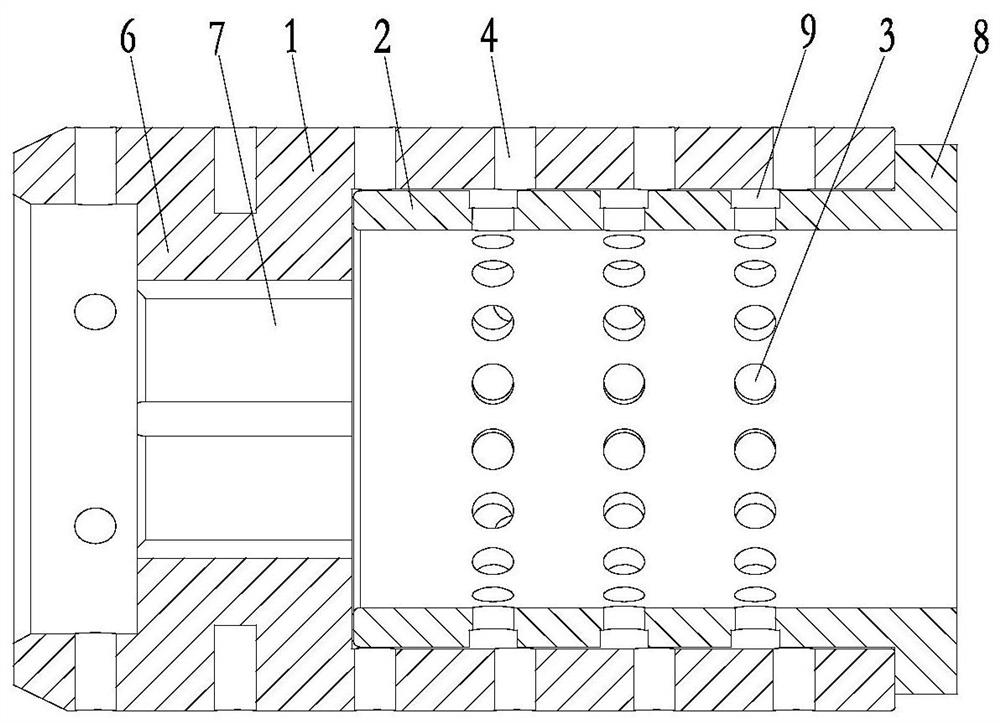
[0015] Such as figure 1 , figure 2 The static and dynamic rings used in an integrated sand mill are installed in the coarse grinding chamber of the sand mill, and include a moving ring 1 and a fixed ring 2. The moving ring 1 has an inner cavity with an open end, and the moving ring 1 One end has a mounting seat 6, and the mounting seat 6 has a shaft hole 7 fixed with the main shaft of the sand mill. The outer peripheral wall of the moving ring 1 along the axial direction of the moving ring 1 is provided with four rows of long hole slot groups arranged at intervals. There are seepage holes 5 distributed axially and located between the long hole slots 4 .

...


PUM


Abstract

The invention relates to a movable and static ring for an integrated sand mill. The movable and static ring comprises a movable ring and a fixed ring, and the movable ring is provided with an inner cavity with an opening in one end; the fixed ring extends into the inner cavity of the movable ring, and is in clearance fit with the wall of the inner cavity of the movable ring; a plurality of rows ofthrough hole sets arranged at intervals are formed in the peripheral wall of the fixed ring in the axis direction of the fixed ring; a plurality of rows of elongated slot sets arranged at intervals are formed in the peripheral wall of the movable ring in the axis direction of the movable ring, and are provided with elongated slots evenly distributed in the circumferential direction; and the through hole sets and the elongated slot sets are arranged in a staggered mode, and communicate with each other through rotation of the movable ring. According to the movable and static ring, through arrangement of the movable ring and the fixed ring which are moved relatively, and by using the shearing effect between the through holes and the elongated slots which are formed in a staggered mode, finegrinding of materials is achieved in cooperation with a grinding medium, so that the conditions of uneven distribution and poor particle size distribution of grinding media after grinding can be overcome properly, and the grinding quality is improved.

Description

technical field [0001] The invention relates to the technical field of sand mills, in particular to a dynamic and static ring used in the coarse grinding chamber of an integrated sand mill. Background technique [0002] Sand mills are used for fine grinding of materials, which can realize continuous processing and continuous discharge of materials. Since traditional sand mills basically use wet grinding, the ground materials need to be dried, resulting in cumbersome grinding process. Therefore, there is an integrated sand mill for dry grinding. The material is ground through the coarse grinding chamber and the fine grinding chamber in the body. In the grinding chamber of the traditional sand mill, grinding discs arranged in a certain order are installed on the main shaft. , with the grinding medium to grind the material, but this conventional grinding disc is likely to cause uneven distribution of the grinding medium and poor particle size distribution after grinding. Cont...

Claims


Application Information

Patent Timeline
Patent Type & Authority Applications(China)
IPC IPC(8): B02C17/18B02C17/10
CPCB02C17/10B02C17/18
Inventor 陆小虎莫铭伟
Owner CHANGZHOU LONGXIN MACHINERY
Why Eureka
Try Eureka