Double-support roller line

A roller table line, double support technology, applied in the direction of roller table, roller column, conveyor objects, etc., can solve the problems of poor gear meshing, long processing cycle, too fast wear, etc., to achieve easy maintenance and replacement, good assembly and flexible assembly sexual effect

Pending Publication Date: 2021-02-05
DALIAN DEXIN M&E TECH ENG
View PDF0 Cites 1 Cited by
  • Summary
  • Abstract
  • Description
  • Claims
  • Application Information

AI Technical Summary

Problems solved by technology

[0003] In the existing bevel gear transmission structure on the market, in the design of most conveying equipment, the installation size of the bevel gear cannot be effectively guaranteed, so the gears mesh poorly, resulting in excessive noise and excessive wear.
At the same time, the current design generally requires drilling holes on the side of the support frame, and requires finishing to meet the assembly requirements of the bearings, which is difficult in the process, and the processing cycle is long and the cost is high.
Due to the impact of the pallet load and other forms, the heavy-duty track line needs double support on each side. For the double-supported track line, based on the installation structure of the track line, the double-supported track line needs to be installed with three columns of profiles. The width depends on the specific It is too wide for application. When making automatic stations, designers often want to use a conveyor line with a narrower side of the roller line, but the existing track line structure cannot do it.

Method used


Image

  • Double-support roller line
  • Double-support roller line
  • Double-support roller line

Examples


Embodiment Construction

[0032] In order to make the structure and function of the present invention clearer, the technical solutions in the embodiments of the present invention will be clearly and completely described below in conjunction with the drawings in the embodiments of the present invention.

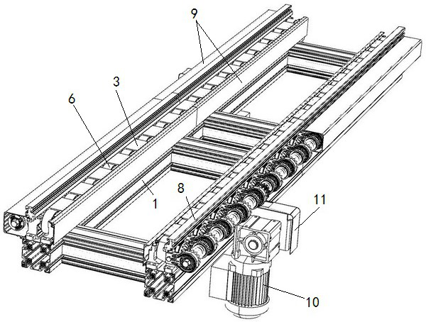
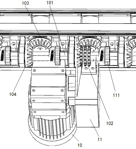
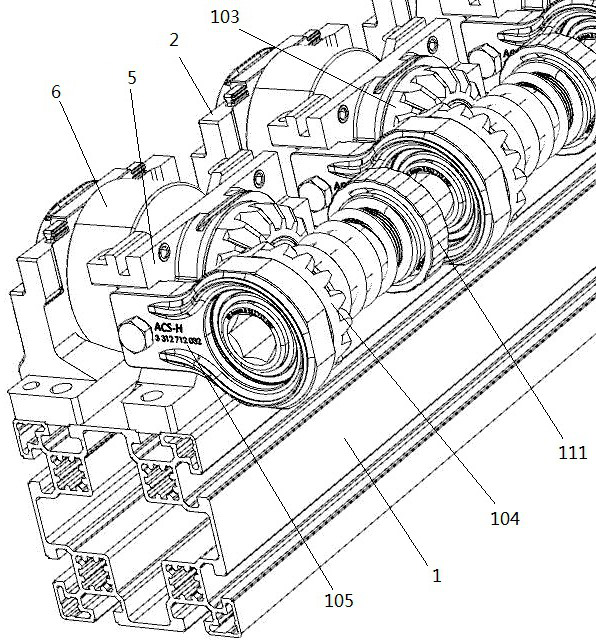
[0033] See attached Figure 1-10, double support roller line, including support frames 1 on both sides parallel to each other, a number of rollers 6 are arranged in sequence on the support frame 1 on each side, the center of the rollers 6 is connected with a roller shaft 4 that rotates synchronously with the rollers 6, and the roller shaft 4, one end is fixed by the auxiliary base 2, the other end of the roller shaft 4 is fixed by the fixed module seat 5, the auxiliary base 2 and the fixed module seat 5 are detachably installed on the support frame 1, and each fixed module seat 5 is installed with a set of The transmission unit that drives the roller shaft to rotate, and the drive mechanism outputs the...


PUM


Abstract

The invention relates to the technical field of rail line conveying, belongs to a standardized tray conveying system established on the basis of a standard aluminum profile, and particularly relates to a double-support roller line. The double-support roller line comprises two side support frames which are parallel to each other, wherein a plurality of rollers are sequentially arranged on the support frame on each side; the centers of the rollers are connected with roller shafts which synchronously rotate with the rollers; one end of each roller shaft is fixed through an auxiliary base; the other end of each roller shaft is fixed through a fixed module seat; the auxiliary bases and the fixed module seats are detachably arranged on the support frames; a set of transmission unit for driving the roller shafts to rotate is arranged on each fixed module seat; and a driving mechanism outputs power to the transmission units. According to the double-support roller line, roller sets are designedinto a standardized module, and a modular assembly mode is adopted, so that the double-support roller line has good assembly flexibility, and can be prepared in batches to improve the manufacturing efficiency of a line body and shorten the delivery cycle; and meanwhile, maintenance and replacement of a single assembly of the whole conveying system are facilitated.

Description

technical field [0001] The invention relates to the technical field of track line conveying, belongs to a standardized pallet conveying system established on the basis of standard aluminum profiles, and is specifically a double-supported roller table line. Background technique [0002] In the standardized pallet system, the roller line is used in actual production as a form of heavy load. The form of the roller table line is generally chain drive and bevel gear drive. Whether it is chain drive or bevel gear drive, when the load of a single pallet is between 300kg-700kg, the accumulation structure is adopted to realize single drive to drive multiple jobs. bit function. [0003] In the existing bevel gear transmission structure on the market, in the design of most conveying equipment, the installation size of the bevel gear cannot be effectively guaranteed, so the gear meshes poorly, resulting in excessive noise and excessive wear. At the same time, the current design genera...

Claims


Application Information

Patent Timeline
IPC IPC(8): B65G13/06B65G39/02
CPCB65G13/06B65G39/02
Inventor 林泉文黄跃进
Owner DALIAN DEXIN M&E TECH ENG
Why Eureka
Try Eureka