Equipment and process for nano-composite electroplating on the inner surface of metal pipe fittings

A metal pipe fitting and nano-composite technology, applied in electrolytic components, electrolytic processes, electrolytic coatings, etc., can solve the problems of limited ability to break aggregates, prone to agglomeration, organic pollution of plating solution, etc. The effect of good plating uniformity and good coating performance

Active Publication Date: 2021-12-07
CISDI RES & DEV CO LTD
View PDF8 Cites 0 Cited by
  • Summary
  • Abstract
  • Description
  • Claims
  • Application Information

AI Technical Summary

Problems solved by technology

The chemical modification method needs to find the appropriate modifier composition and content for different nanoparticles and different plating solution systems. The modification effect is uneven, and it is easy to introduce organic pollution into the plating solution; The effect of making the particles evenly distributed in the container is not enough to break up the agglomerated nanoparticles; ultrasonic dispersion methods include slot ultrasonic and focused ultrasonic. The slot ultrasonic can customize the container size according to the demand, but usually the energy The density is small, the ultrasonic amplitude is about 10 μm, and the ability to break aggregates is limited; the concentrated ultrasonic energy density is high, and the amplitude can be as high as 100 μm or more, which can effectively break the agglomerated nanoparticles. The disadvantage is that the scope of action is small
[0004] For the nano-composite electroplating treatment equipment and methods on the inner surface of metal pipe fittings, no matter using groove-type ultrasonic or energy-concentrating groove depth, due to the limitation of the inner space of the metal pipe, the nano-particles are more likely to agglomerate inside the metal pipe. As a result, the coating on the inner surface of metal pipe fittings is not uniform enough when nanocomposite plating is performed

Method used


Image

  • Equipment and process for nano-composite electroplating on the inner surface of metal pipe fittings
  • Equipment and process for nano-composite electroplating on the inner surface of metal pipe fittings
  • Equipment and process for nano-composite electroplating on the inner surface of metal pipe fittings

Examples


Embodiment Construction

[0047] The implementation of the present invention is illustrated by specific specific examples below, and those skilled in the art can easily understand other advantages and effects of the present invention from the content disclosed in this specification.

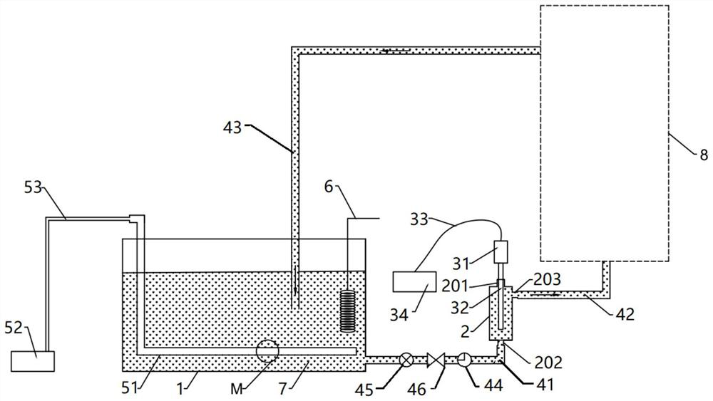
[0048] see in conjunction Figure 1 to Figure 5 , a device for nanocomposite electroplating on the inner surface of metal pipe fittings, comprising:

[0049] A plating solution tank 1 containing a plating solution 7 containing nanoparticles;

[0050]The fluid plating assembly 8 outside the tank, the fluid plating assembly outside the tank includes a metal pipe fitting 81 used as a cathode and an anode post 82 positioned in the metal pipe fitting 81, the inner wall of the metal pipe fitting 81 and the outer wall of the anode post 82 Surrounded by an annular column cavity 801;

[0051] A crushing kettle 2, the crushing kettle 2 is arranged outside the plating solution tank 1;

[0052] Concentrated-energy ultrasonic crush...


PUM


Abstract

The invention discloses a nanocomposite electroplating equipment and process for the inner surface of metal pipe fittings. The equipment includes a plating solution tank, a fluid plating assembly outside the tank, a crushing kettle and an energy-concentrating ultrasonic crushing device. The fluid plating assembly outside the tank includes a The metal pipe fitting used as the cathode and the anode column located in the metal pipe fitting, the inner wall of the metal pipe fitting and the outer wall of the anode column surround the annular column cavity, and the crushing kettle is arranged outside the plating solution tank; the plating solution circulation pipeline will contain the plating solution of nanoparticles From the plating solution tank, it is sent to the crushing tank for ultrasonic crushing, then sent to the annular column cavity, and finally sent back to the plating solution tank. The device of the invention has good timeliness, good flow performance of the plating solution in the annular column cavity, slows down the dynamic re-agglomeration phenomenon of nanoparticles, and has better plating uniformity on the plating layer. In the electroplating process of the present invention, the pre-dispersion treatment is performed first, and then the formal electroplating is performed, so that the nanoparticles can be more uniformly dispersed during the formal electroplating, and the performance of the coating layer is better.

Description

technical field [0001] The invention relates to the technical field of metal surface treatment, in particular to equipment and a process for nanocomposite electroplating on the inner surface of metal pipe fittings. Background technique [0002] Nanocomposite electroplating is highly sought after by researchers because of its excellent coating properties. There are a large number of literature reports on the configuration of nanocomposite electroplating baths and the preparation of coatings. For nanocomposite electroplating, how to make nanomaterials uniformly disperse in the plating solution and coating so as to maintain the nanoscale size and shape is the key and difficulty of the whole technology. Many researchers only add nanoparticles to the plating solution system for macroscopic mixing, but do not pay attention to their microscopic real dispersion state, and do not carry out effective dispersion control on the plating solution containing nanoparticles during the electr...

Claims


Application Information

Patent Timeline
Patent Type & Authority Patents(China)
IPC IPC(8): C25D7/04C25D15/00C25D5/20C25D21/10C25D5/02
CPCC25D5/02C25D5/20C25D7/04C25D15/00C25D21/10
Inventor 冯科王水根漆锐陈欣
Owner CISDI RES & DEV CO LTD
Why Eureka
Try Eureka