
Machining method for gear ring type product

A processing method and product technology, applied in metal processing equipment, metal processing mechanical parts, manufacturing tools, etc., can solve the problems of high scrap rate, difficult to ensure product quality, easy deformation, etc., to overcome heavy weight and product roundness. And the effect of effective control of coaxiality and easy self-control

Inactive Publication Date: 2021-01-29
十堰同创精密机械有限公司
View PDF0 Cites 0 Cited by
  • Summary
  • Abstract
  • Description
  • Claims
  • Application Information

AI Technical Summary

Problems solved by technology

[0003] However, this type of ring gear product has thin wall thickness, large external dimensions, and the weight of the part weighs more than ten kilograms. It has high inertia in high-speed cutting and is easy to shake. The product requirements are very high. The outer roundness, inner hole roundness, The coaxiality must reach 0.02 mm. If a horizontal machine tool is used, the coaxiality must be guaranteed by the beating of the fixture. If the fixture cannot be guaranteed, it will be easily deformed after machining. It is difficult to guarantee product quality during production, and the scrap rate is high.

Method used


Image

  • Machining method for gear ring type product
  • Machining method for gear ring type product
  • Machining method for gear ring type product

Examples


Embodiment Construction

[0031] The technical solution of the present invention will be clearly and completely described below in conjunction with the accompanying drawings, but this embodiment should not be construed as limiting the present invention.

[0032] The present invention as Figure 1 to Figure 9 Shown:

[0033] A method for processing ring gear products,

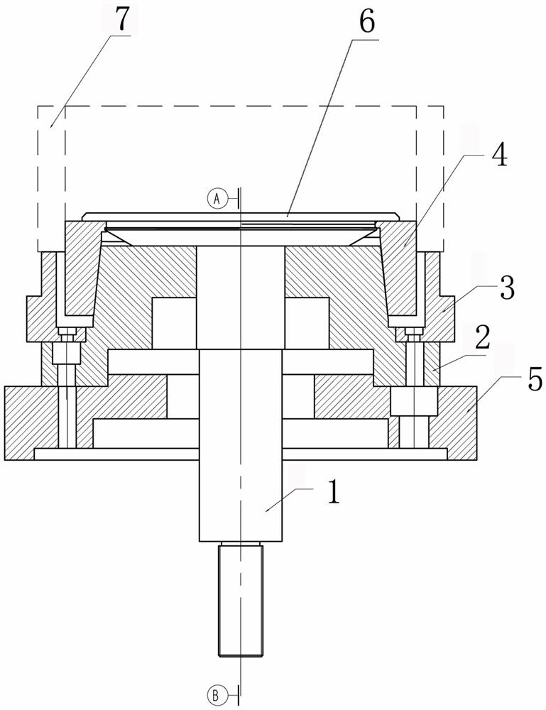
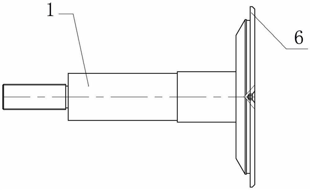
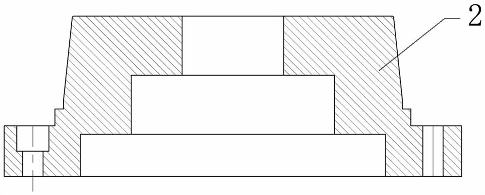
[0034] (1) In order to realize the processing of ring gear products, an auxiliary fixture is adopted. The structure of the auxiliary fixture is: including the pull rod 1, the transition plate 5, the positioning shaft 2, the positioning plate 3 and the spring sleeve 4, and the spring sleeve is fixed on the The upper end of the pull rod, the transition plate, the positioning shaft, and the positioning plate are arranged coaxially from the bottom to the top, and the pull rod passes through the center of the positioning plate, the positioning shaft, and the transition plate, wherein:

[0035] Tie rod 1, the lower end of the pull rod is the...


PUM


Abstract

The invention discloses a machining method for a gear ring type product. In order to achieve machining of the gear ring type product, an auxiliary clamp is adopted, and the auxiliary clamp structurally comprises a pull rod, a transition disc, a positioning shaft, a positioning disc and a spring sleeve, wherein the spring sleeve is fixed to the upper end of the pull rod, the transition disc, the positioning shaft and the positioning disc are coaxially arranged from bottom to top, and the pull rod penetrates through the centers of the positioning disc, the positioning shaft and the transition disc. The method for machining the gear ring type product by adopting the auxiliary clamp comprises the following steps that an existing clamp with elastic core shaft positioning and end surface pressing is used for roughly turning an outer circle firstly; then, a vertical numerical control lathe is used, the used auxiliary clamp is installed on a spindle of the lathe to carry out finish turning onan outer circle and an inner hole of the gear ring type product, and the roundness of the outer circle subjected to finish turning treatment is controlled within 0.05 mm; and finally, a clamp spring groove and a step are cut to complete product machining. The clamp is simple in structure, low in manufacturing cost and convenient to use, ensures the quality of the machined product, and improves theproduction efficiency.

Description

technical field [0001] The invention specifically relates to a processing method for ring gear products. Background technique [0002] At present, although there are many domestic manufacturers that can produce similar products for the planetary gears of the planetary reduction mechanism used in the sub-boxes of heavy-duty gearboxes, the existing processing methods are: the first process is to rough the outer circle first; the second process is to The existing soft-jaw tooling is used, and the inner hole and end face are fine-turned on a horizontal lathe; the tooling used in the third process is also a soft-jaw tool, and the outer circle and end face are fine-turned on a horizontal lathe. [0003] However, this type of ring gear product has thin wall thickness, large external dimensions, and the weight of the part weighs more than ten kilograms. It has high inertia in high-speed cutting and is easy to shake. The product requirements are very high. The outer roundness, inner ...

Claims


Application Information

Patent Timeline
Patent Type & Authority Applications(China)
IPC IPC(8): B23Q3/12
CPCB23Q3/12B23Q2703/10
Inventor 陈翔王波王龙曹国富朱军
Owner 十堰同创精密机械有限公司
Learn More