Pipeline inner wall coating device
A technology for coating devices and pipelines, applied in spraying devices, cleaning hollow objects, spray booths, etc., to achieve the effects of improving work efficiency, avoiding excessive speed, and coating comprehensively
- Summary
- Abstract
- Description
- Claims
- Application Information
AI Technical Summary
Problems solved by technology
Method used
Image

Examples
Embodiment 1
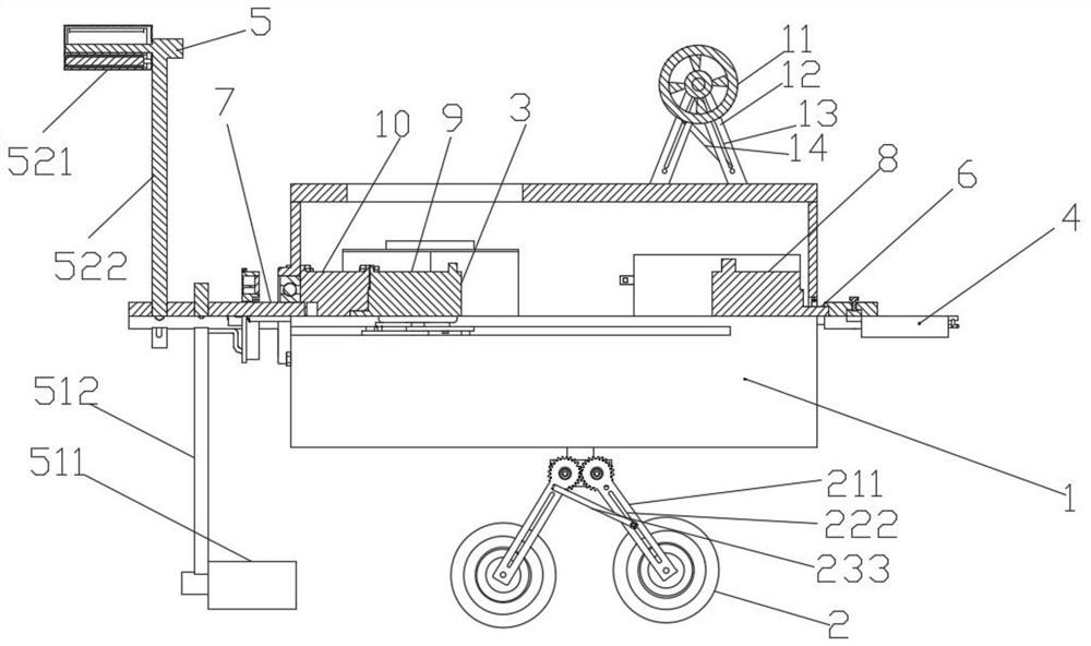
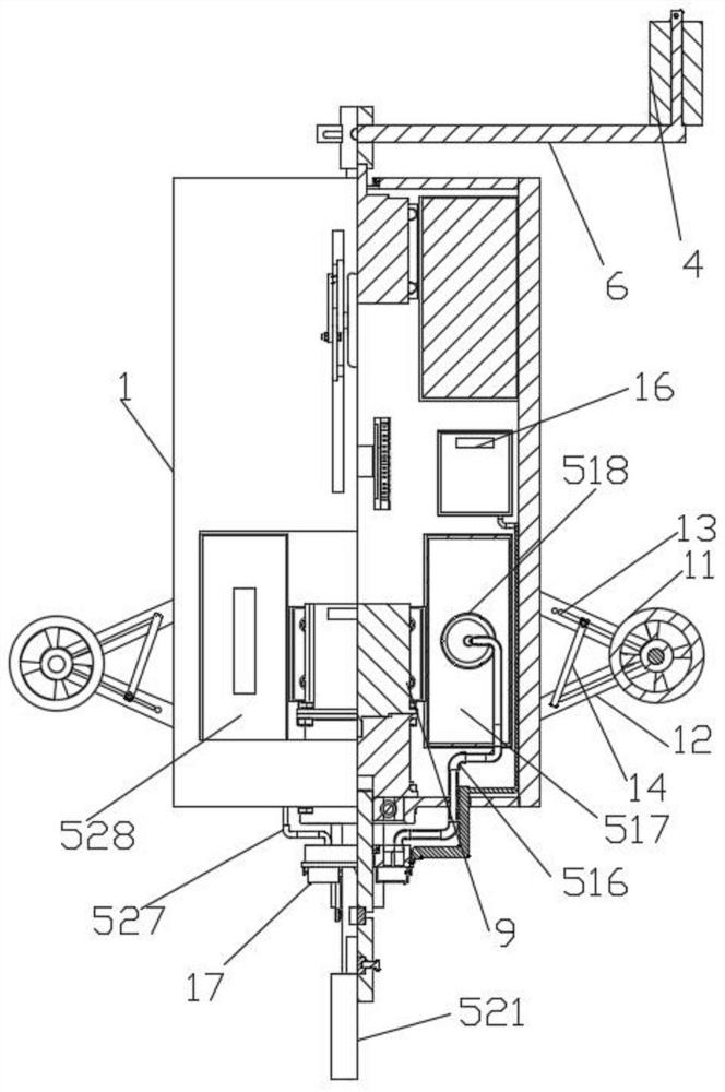
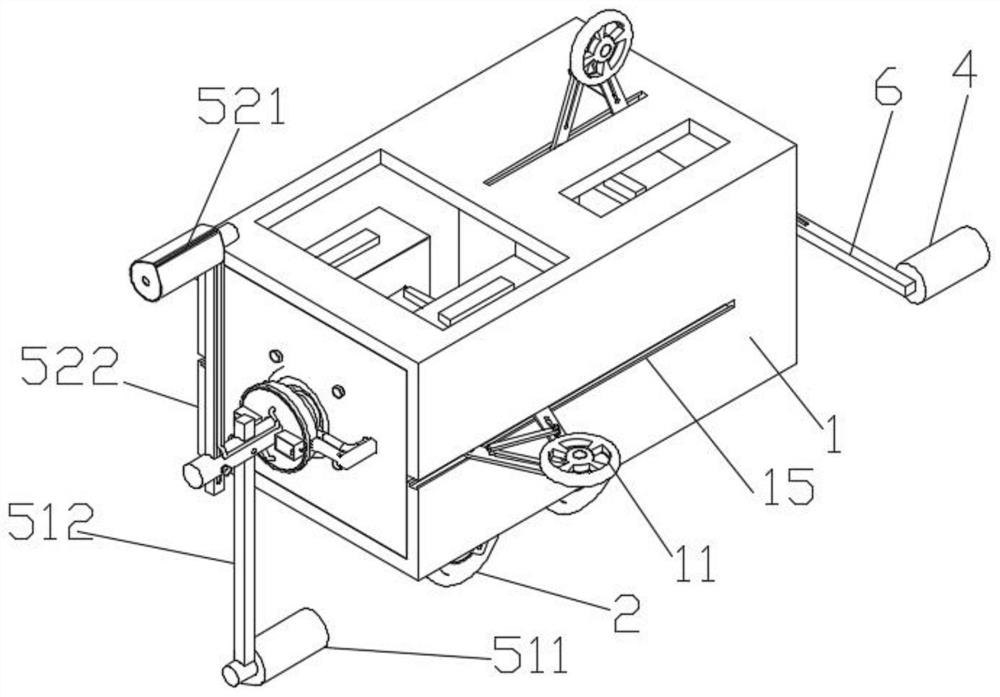
[0049] The embodiment of the present invention provides a pipe inner wall coating device, the specific structure is as follows Figure 1-Figure 3 As shown, it includes a housing 1, the outer bottom surface of the housing 1 is connected with a wheel 2, and there is a rotating device 3 inside the housing 1. Both ends of the rotating device 3 extend outside the housing 1, and one end of the rotating device 3 outside the housing 1 A cleaning device 4 is connected, and the other end of the rotating device 3 is connected with a coating mechanism 5 for coating the inner wall of the pipeline.
[0050] Working principle: Put the device into the pipe whose inner diameter is compatible with the coating device, then turn on the rotating device 3, the rotating device 3 drives the cleaning device 4 to clean the inner wall of the pipe, and the rotating device 3 drives the coating mechanism 5 to clean at the same time Coating is carried out on the inner wall of the final pipe, and then the wh...
Embodiment 2
[0052] This implementation mode is regarded as a preferred embodiment of the present invention, and the specific structure is as follows Figure 1-Figure 3 As shown, it discloses the following improvements on the basis of Embodiment 1. The rotating device 3 includes a cleaning rotating shaft 6 and a coating rotating shaft 7. There are a first motor 8 and a second motor 9 in the housing 1. One end of the cleaning rotating shaft 6 is Extend into the housing 1 and connect with the first motor 8, the other end of the cleaning shaft 6 is connected with the cleaning device 4, one end of the coating shaft 7 extends into the housing 1 and connect with the second motor 9, and the other end of the coating shaft 7 One end is connected with coating mechanism 5 .
[0053] When in use, the first motor 8 is turned on, the first motor 8 works to drive the cleaning shaft 6 to rotate, and the cleaning shaft 6 drives the cleaning device 4 to clean the pipeline. Then open the second motor 9, the...
Embodiment 3
[0056] This implementation mode is regarded as a preferred embodiment of the present invention, and the specific structure is as follows Figure 1-Figure 3 As shown, it discloses the following improvements on the basis of Embodiment 2. The coating mechanism 5 includes a glue assembly 511 and a micro-nano powder assembly 521. The glue assembly 511 is disposed close to the housing 1, and the micro-nano powder assembly 521 is disposed away from the housing 1. .
PUM
 Abstract
Description
Claims
Application Information
 - Generate Ideas
- Intellectual Property
- Life Sciences
- Materials
- Tech Scout
- Unparalleled Data Quality
- Higher Quality Content
- 60% Fewer Hallucinations
Browse by: Latest US Patents, China's latest patents, Technical Efficacy Thesaurus, Application Domain, Technology Topic, Popular Technical Reports.
© 2025 PatSnap. All rights reserved.Legal|Privacy policy|Modern Slavery Act Transparency Statement|Sitemap|About US| Contact US: help@patsnap.com