
Semi-T-shaped three-step metallized safety film capacitor

A technology of metallization and safety film, which is applied in the direction of thin film/thick film capacitors, laminated capacitors, fixed capacitor shells/packages, etc., can solve problems such as poor ability to withstand overcurrent, capacitor heating, and insufficient flow capacity, etc., to achieve improvement The ability to withstand current and the effect of reducing loss

Pending Publication Date: 2021-01-26
嘉善赛晶电容器有限公司 +1
View PDF0 Cites 1 Cited by
  • Summary
  • Abstract
  • Description
  • Claims
  • Application Information

AI Technical Summary

Problems solved by technology

[0004] 1. Due to the existence of a large number of insulation gaps, the loss of components made of safety films is much greater than that of ordinary metallized films of the same specification. The capacitor heats up more seriously during operation, and the high temperature will lead to poor voltage resistance of the base film.
[0005] 2. The safety film designed in the industry usually adopts a coating structure with constant square resistance, but the current on the coating plate is not constant, which leads to insufficient current flow capacity at the coating position with high current density, and poor ability to withstand overcurrent. Difficult to resist when encountering inrush current
[0006] 3. Due to the relatively large area of ​​the module unit design of the traditional T-shaped safety film element, when the fuse is blown, the area of ​​the cut-off plate is too large, so the capacitance loss is too large
When the capacitor is operated continuously for a long time, the capacitance value decays too fast, and the capacitor needs to be replaced frequently to ensure normal operation

Method used


Image

  • Semi-T-shaped three-step metallized safety film capacitor
  • Semi-T-shaped three-step metallized safety film capacitor
  • Semi-T-shaped three-step metallized safety film capacitor

Examples


Embodiment Construction

[0019] Specific embodiments of the present invention will be further described in detail below. It should be understood that the description of the embodiments of the present invention here is not intended to limit the protection scope of the present invention.

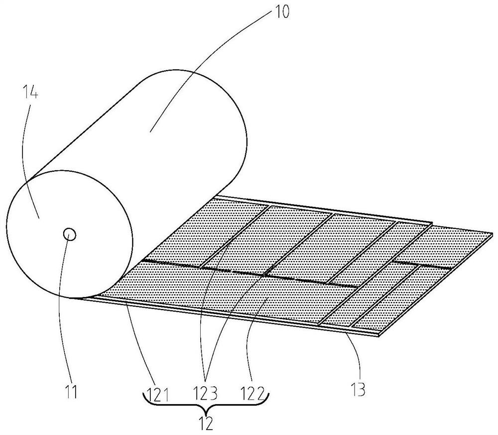
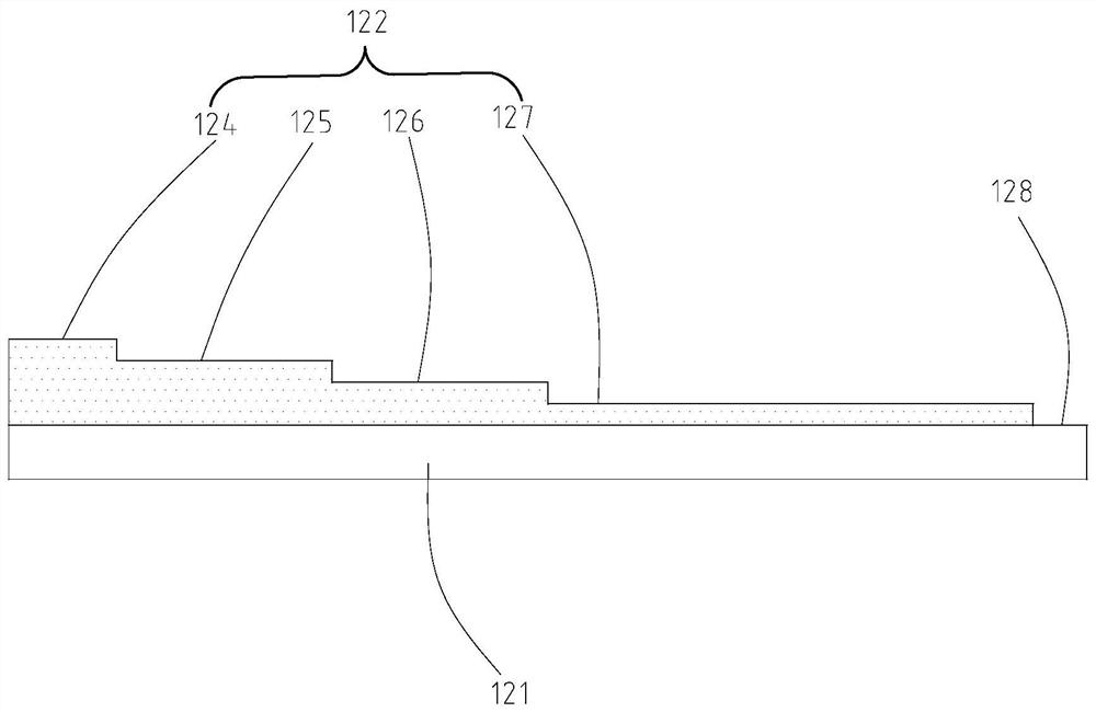
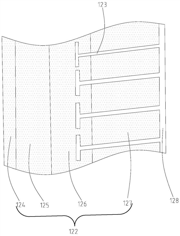
[0020] Such as Figure 1 to Figure 3 As shown, it is a schematic structural diagram of a half-T type three-step metallized safety film capacitor provided by the present invention. It should be noted that the capacitor 10 itself should be a prior art, only some elements are shown in this embodiment, and the rest are not shown. The half-T-shaped three-step metallized safety film capacitor 10 includes an insulating mandrel 11 , and first and second metallized safety films 12 , 13 stacked and wound around the insulating mandrel 11 . The first and second metallized safety films 12, 13 have the same structure. It is conceivable that the half-T-shaped three-step metallized safety film capacitor 10 also includes some other...


PUM


Abstract

A semi-T-shaped three-step metallized safety film capacitor comprises an insulating core rod, a first metallized safety film and a second metallized safety film. The first metallized safety film includes a base film, a metal plating layer, and a T-shaped insulator. The metal coating comprises a thickened region, a low sheet resistance region, a middle sheet resistance region, a high sheet resistance region and a margin region according to the thickness. The thickness of the metal coating is correspondingly adjusted, it can be guaranteed that the current densities of all the parts of the metalcoating are basically consistent in the current magnitude changing process, the current bearing capacity of the metallized safety film is greatly improved, and then the loss of the first metallized safety film and the loss of the second metallized safety film are reduced. The T-shaped insulating part is only arranged on the middle sheet resistance area and the high sheet resistance area, so that insulating substances on the metallized safety film are greatly reduced, the area of each film coating area divided by the T-shaped insulating part is correspondingly reduced, and therefore, when a certain film coating area is cut off, the lost capacitance is correspondingly reduced, and the capacitor is more durable.

Description

technical field [0001] The invention relates to the technical field of power electronic capacitors such as DC support capacitors for flexible engineering and rail locomotives, and in particular to a half-T-shaped three-step metallized safety film capacitor. Background technique [0002] At present, metallized film capacitors are becoming more and more popular due to their good self-healing properties and pressure resistance, and metallized film capacitors are the most important raw materials for their production. The thinner the coating thickness of the metallized film, the higher its square resistance, and the film with high square resistance has better self-healing performance but poor flow capacity. On the contrary, the thicker the coating, the smaller the square resistance, the lower the self-healing ability but the better the flow ability. When self-healing is excessive, a large amount of self-healing energy accumulated in a short period of time will also cause the bas...

Claims


Application Information

Patent Timeline
Patent Type & Authority Applications(China)
IPC IPC(8): H01G4/33H01G4/224
CPCH01G4/224H01G4/33
Inventor 邓光昭尤畅周幸福张鑫苏闽榕
Owner 嘉善赛晶电容器有限公司
Learn More