
Transformer and converter valve charging test circuit and method

A technology for testing circuits and converter valves, which is applied in the field of circuits and can solve problems such as the inability to meet the needs of testing

Pending Publication Date: 2021-01-26
NORTH CHINA ELECTRICAL POWER RES INST +2
View PDF0 Cites 4 Cited by
  • Summary
  • Abstract
  • Description
  • Claims
  • Application Information

AI Technical Summary

Problems solved by technology

Usually, the wharf can only provide 10kV low-voltage power supply, and the power supply capacity is only 3-5MW, which cannot meet the test needs at all.

Method used


Image

  • Transformer and converter valve charging test circuit and method
  • Transformer and converter valve charging test circuit and method
  • Transformer and converter valve charging test circuit and method

Examples


Embodiment Construction

[0032] The technical solutions in the embodiments of the present invention will be clearly and completely described below in conjunction with the accompanying drawings in the embodiments of the present invention. Obviously, the described embodiments are only part of the embodiments of the present invention, not all of them. Based on the implementation manners in the present invention, all other implementation manners obtained by persons of ordinary skill in the art without making creative efforts belong to the scope of protection of the present invention.

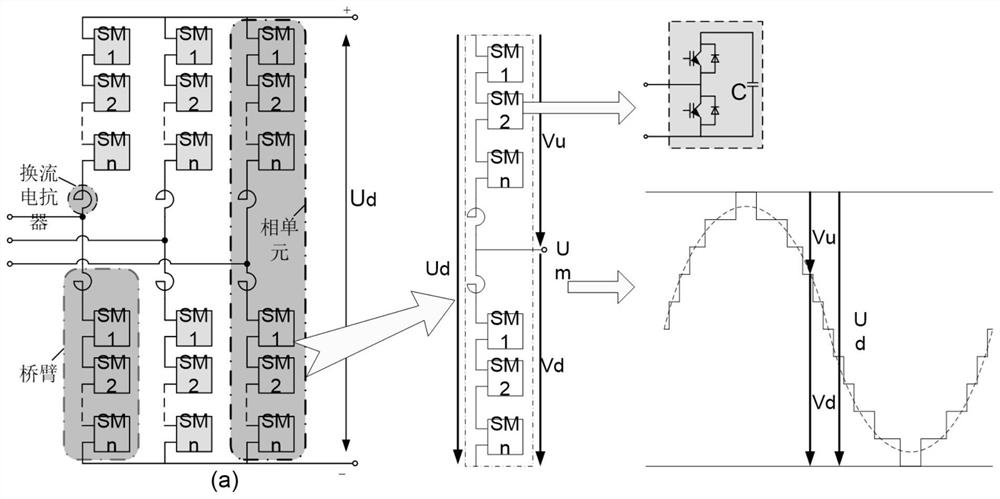
[0033] The main structure of the half-bridge MMC converter is as follows: figure 1 As shown, the converter is composed of three phase units, each phase unit includes two upper and lower bridge arms, and the bridge arm branches are composed of many MMC sub-modules connected in series. Each MMC-type sub-module is composed of IGBT, capacitor, diode, thyristor and other components, and the switching on and off of the capacitor...


PUM


Abstract

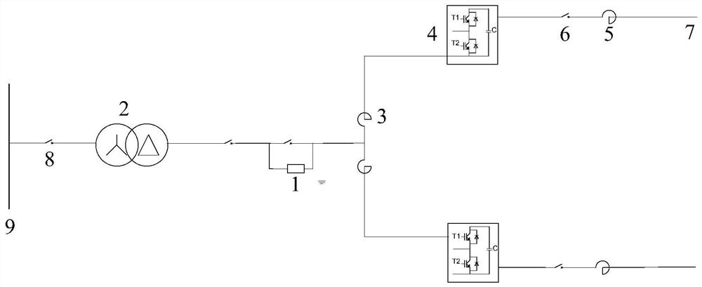
The invention provides a transformer and converter valve charging test circuit and method. The transformer and converter valve charging test circuit comprises an AC test power supply, a test module with one end coupled to the output end of the test power supply, and a parallel DC bridge arm coupled to the other end of the test module. The test module is used for adjusting the output voltage of thealternating current test power supply, so that the voltage of the input end of the parallel direct current bridge arm is increased from zero to a set voltage within a set duration. The invention provides the test method and the test platform for charging and unlocking the transformer and the current converter by using the medium-low voltage test power supply, the requirement on the capacity of the test power supply can be lowered, and in the unlocking process of the current converter, the impact current is reduced by adopting a method for unlocking the current converter under the condition oflow voltage. And after the converter is unlocked, a method of gradually increasing the input alternating voltage of the converter and charging the converter along with a method of increasing the direct voltage is adopted.

Description

technical field [0001] The invention relates to the field of circuit technology, and more specifically, to a charging test circuit and method for a converter transformer and a converter valve. Background technique [0002] Flexible DC transmission technology is a new type of DC transmission technology based on voltage source converters, turn-off devices and pulse width modulation technology. Compared with the traditional thyristor-based current source DC transmission technology, the flexible DC transmission technology has the advantages of high controllability, convenient design and construction, small footprint and no communication between converter stations. It has obvious advantages in grid-connected power generation, island power supply, and urban grid power supply. Flexible DC transmission has developed rapidly in recent years. [0003] Offshore wind power grid connection is an important application of flexible direct current transmission, and the flexible direct curr...

Claims


Application Information

Patent Timeline
IPC IPC(8): G01R31/62G01R19/155
CPCG01R19/155G01R31/62
Inventor 辛光明王丰蔡巍谢欢刘苗陈瑞王晓斐李善颖李长宇
Owner NORTH CHINA ELECTRICAL POWER RES INST
Learn More