
Rapid pre-cooling concrete dam refrigeration equipment

A technology for concrete dams and refrigeration equipment, which is used in household refrigeration devices, lighting and heating equipment, cooling fluid circulation devices, etc., can solve the problem that dust cannot be cleaned out.

Inactive Publication Date: 2021-01-22
西安思明制冷设备工程有限公司
View PDF2 Cites 0 Cited by
  • Summary
  • Abstract
  • Description
  • Claims
  • Application Information

AI Technical Summary

Problems solved by technology

[0007] The purpose of the present invention is to solve the problem that the dust produced by the rapid pre-cooling concrete dam refrigeration equipment in the prior art cannot be cleaned out, and proposes a rapid pre-cooling concrete dam refrigeration equipment

Method used


Image

  • Rapid pre-cooling concrete dam refrigeration equipment
  • Rapid pre-cooling concrete dam refrigeration equipment

Examples


Embodiment 1

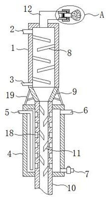
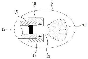
[0023] Example 1 as Figure 1-2 As shown, this rapid precooling concrete dam refrigeration equipment includes a rectangular pipe 1, an aggregate feed pipe 2, a cold air inlet pipe 3, a barrel body 4, a liquid ammonia inlet pipe 5, an ammonia gas outlet pipe 6 and a liquid ammonia outlet pipe 6. The ammonia outlet pipe 7 is fixedly connected to the inner wall of the rectangular pipe 1 with a plurality of evenly staggered first slow flow plates 8, the rectangular pipe 1 is provided with an opening at the bottom, and the opening position is fixedly connected with a tapered bucket 9, the tapered The bottom end of the bucket 9 is fixedly connected with a feed pipe 10, and the feed pipe 10 is arranged through the barrel body 4, and the inner wall of the feed pipe 10 located in the barrel body 4 is fixedly connected with a plurality of evenly staggered second buffers. The flow plate 11, the aggregate feeding pipe 2 is fixedly connected with the position near the top of the rectangula...

Embodiment 2

[0025] Embodiment 2 is on the basis of embodiment 1 such as figure 1 As shown, its feed pipe 10 is made of copper material, and a plurality of evenly distributed grooves 18 are provided on the outer wall of the feed pipe 10 located in the barrel body 4 to increase the contact area and improve the pre-cooling efficiency.

Embodiment 3

[0026] Embodiment 3 is such as on the basis of embodiment 1 figure 1 As shown, the air outlet of its cold air inlet pipe 3 is located below the first slow flow plate 8 to prevent the aggregate from entering the cold air inlet pipe 3 .


PUM


Abstract

The invention relates to the technical field of refrigeration equipment, and discloses rapid pre-cooling concrete dam refrigeration equipment. The equipment comprises a rectangular pipeline, an aggregate feeding pipe, a cold air inlet pipe, a barrel body, a liquid ammonia inlet pipe, an ammonia gas outlet pipe and a liquid ammonia outlet pipe. A plurality of first slow flow plates evenly distributed in a staggered manner are fixedly connected to the inner wall of the rectangular pipeline. The bottom of the rectangular pipeline is provided with an opening, the opening is fixedly communicated with a conical hopper, the bottom end of the conical hopper is fixedly communicated with a material guide pipe, the material guide pipe penetrates through the barrel body, and a plurality of second slowflow plates which are evenly distributed in a staggered manner are fixedly connected to the position, located in the barrel body, of the inner pipe wall of the material guide pipe. The aggregate feeding pipe fixedly communicates with the position, close to the top, of the rectangular pipeline, and the cold air inlet pipe fixedly communicates with the position, close to the bottom, of the rectangular pipeline. The pre-cooling effect and the pre-cooling efficiency of the concrete aggregate are effectively improved, and dust in the aggregate can be conveniently cleaned and collected.

Description

technical field [0001] The invention relates to the technical field of refrigeration equipment, in particular to a rapid precooling concrete dam refrigeration equipment. Background technique [0002] The amount of concrete used in the normal state of the dam is large, and the required concrete temperature is very low. Due to reasons such as the moisture content of sand and stones, the amount of water that can be added freely is very small, so the amount of ice added to the concrete is very limited, so the aggregate also needs to be reduced to a very low level in advance. Low temperature, two kinds of aggregate refrigeration systems are generally used in the prior art, one is water cooling, the other is air cooling, the traditional water cooling or air cooling cooling speed is slow, and rapid pre-cooling is not possible during pre-cooling . [0003] In the patent of Chinese patent authorization number CN210980467U, a kind of fast precooling concrete dam refrigeration equipme...

Claims


Application Information

Patent Timeline
IPC IPC(8): F25D3/10F25D17/06F25D23/00F25D23/06
CPCF25D3/10F25D17/06F25D23/00F25D23/06
Inventor 胡友
Owner 西安思明制冷设备工程有限公司
Learn More