
Radial adjusting and fastening device for ultra-precision optical machining of grazing incidence mirror

A reflective mirror, ultra-precise technology, applied to the surface coating device, coating, etc., can solve the problems of the adhesion between the knife lens and the fastening seat, the decrease of the mirror surface precision, and the lens sinking, etc., to increase the The effective bonding area, improving the bonding force, and solving the effect of mirror surface shape error

Active Publication Date: 2021-01-22
CHANGCHUN NORMAL UNIVERSITY
View PDF9 Cites 0 Cited by
  • Summary
  • Abstract
  • Description
  • Claims
  • Application Information

AI Technical Summary

Problems solved by technology

[0004] In order to solve the phenomenon of lens deformation, burst, crack, gnawing and other phenomena caused by the small gap between the lens and the fastening seat in the process of processing the X-ray grazing incident mirror surface, as well as the adhesion between the lens and the fastening seat In order to solve the problems of lens sinking and mirror surface precision reduction caused by insufficient joint strength, the present invention provides an ultra-precision optical grazing incidence mirror processing radial adjustment and fastening device, which is mainly suitable for processing X-ray grazing incidence mirror mirrors

Method used


Image

  • Radial adjusting and fastening device for ultra-precision optical machining of grazing incidence mirror
  • Radial adjusting and fastening device for ultra-precision optical machining of grazing incidence mirror
  • Radial adjusting and fastening device for ultra-precision optical machining of grazing incidence mirror

Examples


Embodiment Construction

[0043]The present invention will be further described in detail below in conjunction with the drawings.

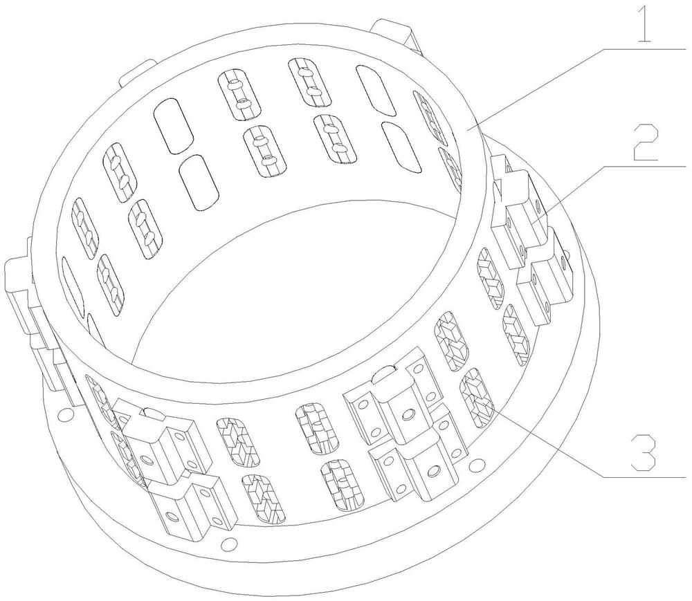
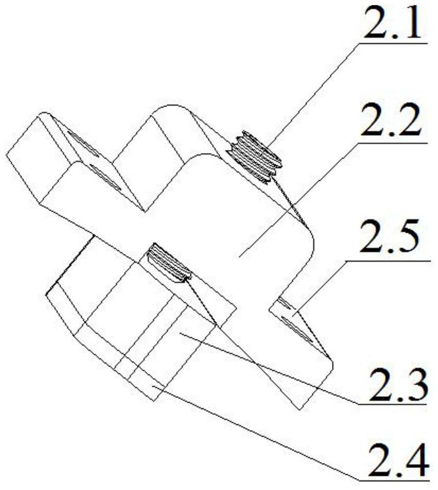
[0044]Such asFigure 1 to Figure 4As shown, an ultra-precision optical grazing incidence mirror processing radial adjustment and fastening device of the present invention mainly includes: a fastening seat 1, a plurality of radial adjustment mechanisms 2 and a plurality of glue blocks 3; The adjustment mechanism 2 and a plurality of glue blocks 3 are all installed on the fixing seat 1, and the reflector is installed in the fixing seat 1. The radial adjustment mechanism 2 is used to adjust the radial direction of the reflector in the fixing seat 1. Position, the glue block 3 is used to adjust the circumferential position of the reflector in the fixing seat 1.

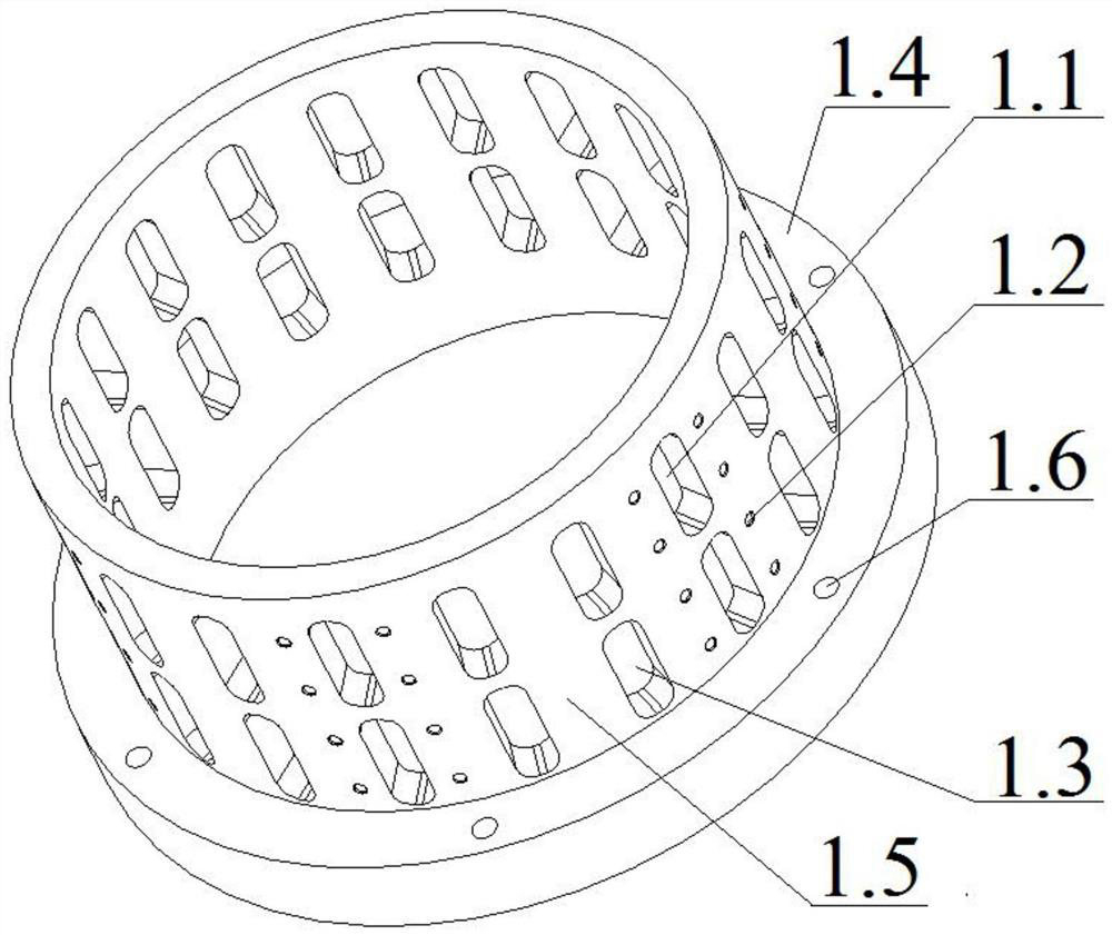
[0045]Such asfigure 2 As shown, the fastening seat 1 mainly includes an annular chassis 1.4 and a hollow cylinder 1.5. The annular chassis 1.4 is fixed at the lower end of the hollow cylinder 1.5. The inner wall of the annular bas...


PUM


Abstract

The invention discloses a radial adjusting and fastening device for ultra-precision optical machining of a grazing incidence mirror, and relates to the field of optical design and fabrication. The radial adjusting and fastening device comprises a fastening seat used for mounting the mirror, a plurality of radial adjusting mechanisms installed on the fastening seat and a plurality of fixing adhesive blocks installed on the fastening seat; the radial position of the mirror in the fastening seat is adjusted through the radial adjusting mechanisms; and the circumferential position of the mirror inthe fastening seat is adjusted through the fixing adhesive blocks. The radial position of the mirror is fastened through the radial adjusting mechanisms, so that the problem that the mirror sinks dueto the influence of gravity in the machining process can be effectively solved, the coaxiality between the axis of a mirror surface and the axis of the fastening seat is improved; and the coaxialityshould be controlled within 0.1[mu]m, so that the machining precision of the surface shape of the mirror surface is improved. Adhesive injection is realized for two times through the fixing adhesive blocks, so that the effective adhesive bonding area between the mirror and the fastening seat can be increased; the bonding force between the mirror and the fastening seat is improved, so that the stable fastening effect is achieved, and radial fixing and circumferential fixing of the mirror in the machining process are realized.

Description

Technical field[0001]The invention relates to the technical field of optical design and manufacturing, in particular to a radial adjustment and fastening device for processing an ultra-precision optical grazing incidence mirror.Background technique[0002]X-ray astronomical observations are of great significance to research in the fields of deep space exploration, space weather forecasting, and high-precision automatic navigation of interstellar space flight. X-rays have the characteristics of short wavelength and strong penetrability. The X-rays received by the X-ray detector are required to be grazing incident on the optical surface at a small angle to obtain a large reflectivity. The widely used grazing incidence optical system mainly has three structures: K-B type, Wolter type and lobster eye type. The structure of the K-B type system is relatively simple, which is suitable for medium-resolution imaging and spectral observation of weak light sources. It has not been used as a sate...

Claims


Application Information

Patent Timeline
Patent Type & Authority Applications(China)
IPC IPC(8): B05C13/02
CPCB05C13/02
Inventor 孙立巍丁颂张小奇蒋东霖马子玉孙嘉彬
Owner CHANGCHUN NORMAL UNIVERSITY
Learn More