Steam ironing rewinding machine for cloth processing
An ironing and rewinding machine and steam technology, which is applied in the direction of fabric steam/steaming treatment, thin material treatment, winding strips, etc. problems, to save work time, improve work efficiency, and ensure the effect of flatness
- Summary
- Abstract
- Description
- Claims
- Application Information
AI Technical Summary
Problems solved by technology
Method used
Image
Examples
Embodiment 1
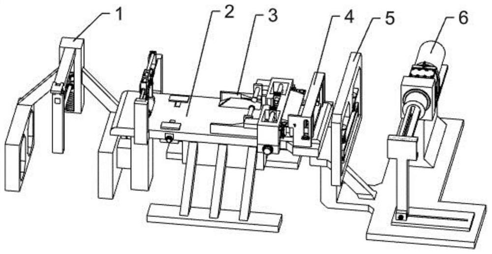
[0091] A cloth processing steam ironing and rewinding machine, such as Figure 10-11 As shown, it includes: horizontal feeding mechanism, ironing frame 4, ironing board 401, ironing moving block 402, ironing extension spring 403, steam ironing device 404, L-shaped board 405, manual board 4051, connecting shaft 4052, card position block 4053, force spring 4054 and automatic material receiving mechanism. There is a rectangular protrusion on the ironing board 401. The two outermost shelf plates of the ironing frame 4 are fixed on the ironing board 401. The ironing frame 4 The two inside shelves are fixedly connected to the rectangular projections of the ironing board 401. There are sliding holes on the front side of the ironing frame 4. There are two ironing moving blocks 402. The ironing moving block 402 in the front slides on the On the two shelves on the front side of the ironing frame 4, the ironing moving block 402 at the rear slides on the two shelves on the rear side of th...
Embodiment 2
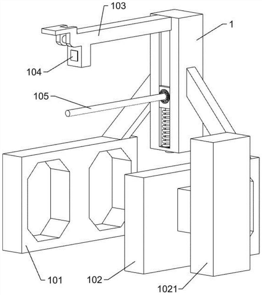
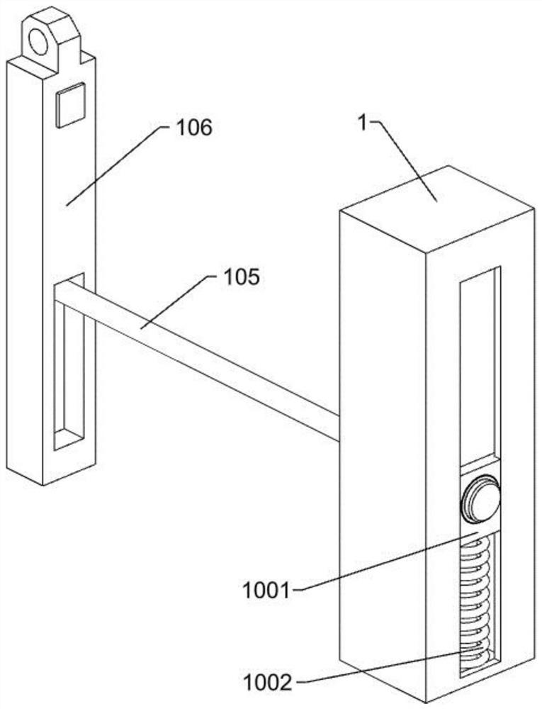
[0094] On the basis of Example 1, such as Figure 1-3 and Figure 13-15 As shown, the horizontal feeding mechanism includes a feeding square column 1, a column slider 1001, a column spring 1002, a double-hole plate 101, a single-hole plate 102, a plate support column 1021, a magnetic support rod 103, a powerful magnet 104, a supply Material shaft 105 and magnetic rotating rod 106, feeding square column 1 is a hollow rectangular column with holes, and column slider 1001 is slidably connected in feeding square column 1, and column slider 1001 is U-shaped. The cylindrical rod passes through the cylindrical hole at the bottom of the feeding square column 1, and the column spring 1002 is sleeved on the cylindrical rod of the column slider 1001, and the column spring 1002 is located between the column slider 1001 and the bottom of the feeding square column 1. The plate 101 is fixed on the right side of the feeding square column 1, the single-hole plate 102 is fixed on the left side...
Embodiment 3
[0099] On the basis of Example 1, such as Figure 4-9 and Figure 12 As shown, a positioning and pressing mechanism is also included, and the positioning and pressing mechanism includes an operating table 2, a C-shaped frame 201, a sliding support 202, a push-pull rod 203, a pressing sliding rod 204, a pressing spring 2041, and a pressing connecting rod 2042 , pressing roller 2043, embossed plate 205, first rotating screw rod 206 and positioning slide block 207, operating platform 2 is fixedly connected on the plate support column 1021, C-shaped frame 201 is fixedly connected on the left end of operating platform 2, and sliding support 202 Fixed on the upper side of the C-shaped frame 201, a rectangular through hole is opened on the column leg on the front side of the sliding support 202, the front end of the push-pull rod 203 passes through the rectangular through-hole on the sliding support 202, and the two protrusions on the upper side of the push-pull rod 203 The block is...
PUM
 Abstract
Description
Claims
Application Information
 - R&D
- Intellectual Property
- Life Sciences
- Materials
- Tech Scout
- Unparalleled Data Quality
- Higher Quality Content
- 60% Fewer Hallucinations
Browse by: Latest US Patents, China's latest patents, Technical Efficacy Thesaurus, Application Domain, Technology Topic, Popular Technical Reports.
© 2025 PatSnap. All rights reserved.Legal|Privacy policy|Modern Slavery Act Transparency Statement|Sitemap|About US| Contact US: help@patsnap.com


