
Motor for unmanned aerial vehicle and assembling method thereof

An unmanned aerial vehicle and interference fit technology, which is used in electromechanical devices, manufacturing motor generators, electrical components, etc., can solve the problems of insufficient stability of heat-generating rotor magnets, shortened bearing service life, and large loss of stator windings. The effect of eliminating the sticking process, improving the power density and reducing the loss

Active Publication Date: 2021-01-15
杨士兵
View PDF4 Cites 0 Cited by
  • Summary
  • Abstract
  • Description
  • Claims
  • Application Information

AI Technical Summary

Problems solved by technology

[0003] In the prior art, the stator core of the UAV motor is integrated, and the stator winding is stuffed in from the gap on each slot of the stator core. It is very troublesome to get off the wire, and the wire is very loose, and there must be a margin for the wire. Otherwise, it is difficult to put it in, the two ends of the stator winding protrude longer, the loss of the stator winding is large, and the power density is low
[0004] The rotor magnet of the UAV motor is pasted with an indexing plate, which requires precise positioning operations, and the heating of the motor will make the pasted magnet unstable.
[0005] At present, the UAV motor is air-cooled by the airflow rotated by the blades. The heat dissipation effect is not good, which will shorten the service life of the bearing. At the same time, the increase in heat will also make the rotor magnet unstable, which needs to be improved.

Method used


Image

  • Motor for unmanned aerial vehicle and assembling method thereof
  • Motor for unmanned aerial vehicle and assembling method thereof
  • Motor for unmanned aerial vehicle and assembling method thereof

Examples


Embodiment Construction

[0041] The present invention will be further described below in conjunction with accompanying drawing and specific embodiment:

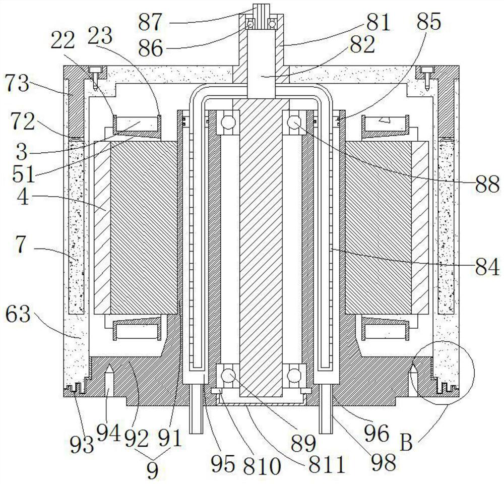
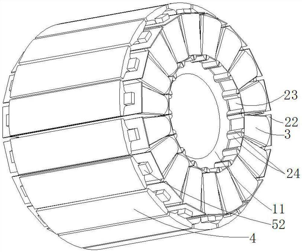
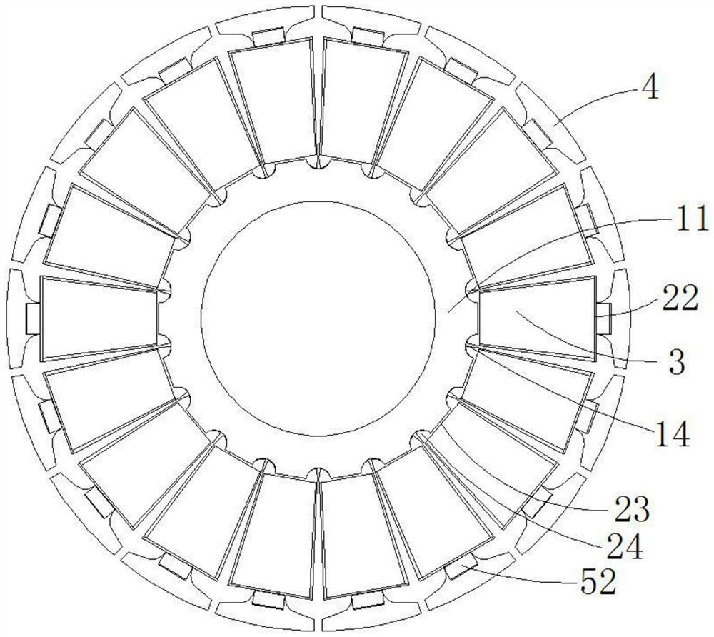
[0042] Such as Figure 1 to Figure 12 Shown, a kind of motor that is used for unmanned aerial vehicle comprises stator, rotor and stator bracket 9, and described stator comprises first stator iron core 1, winding insulation skeleton 2, stator winding 3, second stator iron core 4 and Wedge key 5, the stator core of this embodiment is a split type, that is, divided into a first stator core 1 and a second stator core 4, the first stator core 1 includes an iron core ring 11 and a circumferential uniform For the iron core branches 12 arranged on the outer wall of the iron core ring body 11 , the inner ends of two adjacent iron core branches 12 cooperate with the outer wall of the iron core ring body 11 to form an arc-shaped groove 14 .

[0043]The outer end of the iron core branch 12 is provided with an outwardly protruding iron core socket 13, and the i...


PUM


Abstract

The motor comprises a stator, a rotor and a stator support, the stator is installed on the outer wall of the stator support in an interference fit mode, the rotor is located on the periphery of the stator, and the stator comprises a first stator iron core, a winding insulation framework, a stator winding, a second stator iron core and a wedge-shaped key. The stator support comprises a stator support inner ring part and a stator support outer ring part which are integrally formed, the inner wall of the iron core ring body is in interference fit with the outer wall of the stator support inner ring part, and an inner ring part groove is formed in the upper end of the stator support inner ring part. The rotor support comprises a rotor ring part and a support disc part, the upper end of the rotor ring part is provided with magnetic steel grooves, the magnetic steel is circumferentially and evenly distributed in the magnetic steel grooves, and the rotating shaft and the support disc part areinstalled in an interference fit mode. The motor is simple and convenient to assemble, good in heat dissipation effect and good in sealing effect.

Description

technical field [0001] The invention relates to the technical field of motors, in particular to a motor used for drones and an assembly method thereof. Background technique [0002] At present, drones have been widely used, and the demand for motors of drones has increased dramatically. The general characteristic of the motor of the UAV is that the stator is inside and the rotor is outside. [0003] In the prior art, the stator core of the UAV motor is integrated, and the stator winding is stuffed in from the gap on each slot of the stator core. It is very troublesome to get off the wire, and the wire is very loose, and there must be a margin for the wire. Otherwise, it is difficult to put it in, the two ends of the stator winding protrude longer, the loss of the stator winding is large, and the power density is low. [0004] The rotor magnet of the UAV motor is pasted with an indexing plate, which requires precise positioning operations, and the heating of the motor will ...

Claims


Application Information

Patent Timeline
IPC IPC(8): H02K1/12H02K1/18H02K1/27H02K1/28H02K1/30H02K3/46H02K9/19H02K9/193H02K15/02H02K15/03
CPCH02K1/12H02K1/187H02K1/2786H02K1/28H02K1/30H02K3/46H02K9/19H02K9/193H02K15/02H02K15/026H02K15/03
Inventor 杨士兵
Owner 杨士兵
Learn More