Distributed multi-shaft gas turbine and hybrid power system
A gas turbine and hybrid power technology, which is applied in the direction of gas turbine devices, machines/engines, fuel cells, etc., can solve the problems of difficult design of single-shaft gas turbines, improve system efficiency and layout flexibility, improve design flexibility and efficiency, Easy to use effect
- Summary
- Abstract
- Description
- Claims
- Application Information
AI Technical Summary
Problems solved by technology
Method used
Image

Examples
Embodiment 1
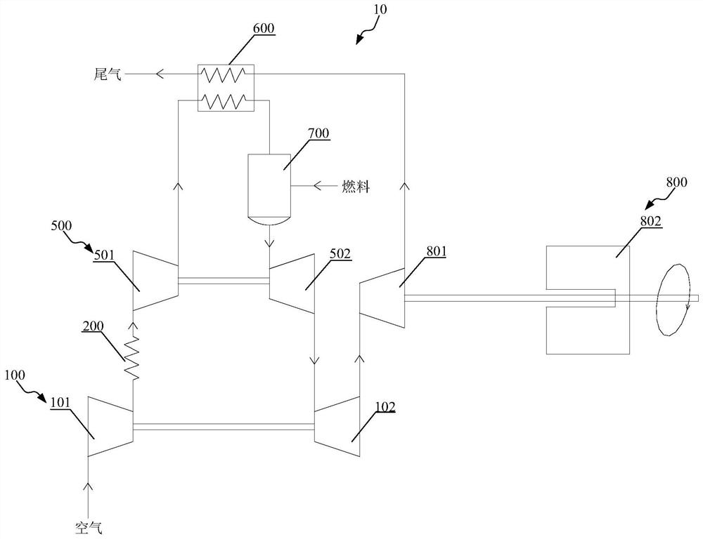
[0065] Such as figure 1 As shown, this embodiment provides a distributed multi-shaft gas turbine. The distributed multi-shaft gas turbine 10 includes: a low-pressure shaft module 100, a first intercooler module 200, and a high-pressure shaft module 500 that are independent of each other and connected through pipelines. , regenerator module 600, combustor module 700 and power turbine drive module 800,
[0066] The low-pressure shaft module 100 includes: a low-pressure compressor 101 and a low-pressure turbine 102, the low-pressure compressor 101 and the low-pressure turbine 102 are coaxially connected through bearings;
[0067] The high-pressure shaft module 500 includes: a high-pressure compressor 501 and a high-pressure turbine 502, the high-pressure compressor 501 and the high-pressure turbine 502 are coaxially connected through bearings;
[0068] The power turbine drive module 800 includes: a power turbine 801 and a power output unit 802, the power turbine 801 and the powe...
Embodiment 2
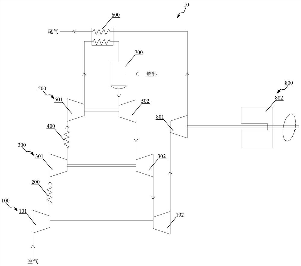
[0078] Such as figure 2As shown, this embodiment provides a distributed multi-shaft gas turbine, which is different from Embodiment 1 in that the distributed multi-shaft gas turbine 10 in this example further includes: at least one middle final shaft module 300, and the middle final shaft module 300 It includes: an intermediate pressure compressor 301 and an intermediate pressure turbine 302, the intermediate pressure compressor 301 and the intermediate pressure turbine 302 are coaxially connected through bearings, at this time, the intermediate pressure compressor 301 is connected to the first room Between the air outlet of the cooler module 200 and the air inlet of the high-pressure compressor 501, the medium-pressure turbine 302 is connected between the air outlet of the high-pressure turbine 502 and the air inlet of the low-pressure turbine 102; When the distributed multi-shaft gas turbine 10 includes two or more intermediate pressure shaft modules 300, multiple intermedi...
Embodiment 3
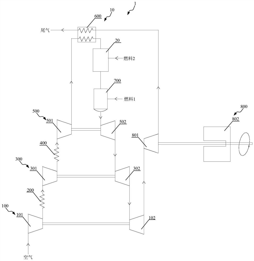
[0086] Such as image 3 As shown, this embodiment provides a hybrid power system, and the hybrid power system 1 includes: the distributed multi-shaft gas turbine 10 and the high-temperature fuel cell 20 as described in Embodiment 1 or Embodiment 2, wherein the high-temperature The fuel cell 20 is connected between the air outlet of the regenerator module 600 and the air inlet of the combustor module 700; at this time, the distributed multi-shaft gas turbine 10 and the high-temperature fuel cell 20 are the direct top layer coupling, that is, the air that has been heat-exchanged by the regenerator module 600 directly enters the high-temperature fuel cell 20 and undergoes an electrochemical reaction with the fuel 2 therein, so as to heat the air that has not participated in the reaction, thereby further improving the air entering the high-temperature fuel cell 20. The temperature of the air in the combustor module 700 is improved to improve the combustion efficiency of the system...
PUM
 Abstract
Description
Claims
Application Information
 - R&D
- Intellectual Property
- Life Sciences
- Materials
- Tech Scout
- Unparalleled Data Quality
- Higher Quality Content
- 60% Fewer Hallucinations
Browse by: Latest US Patents, China's latest patents, Technical Efficacy Thesaurus, Application Domain, Technology Topic, Popular Technical Reports.
© 2025 PatSnap. All rights reserved.Legal|Privacy policy|Modern Slavery Act Transparency Statement|Sitemap|About US| Contact US: help@patsnap.com