
Spliced floor combination

A splicing, splicing board technology, applied in the direction of floor, covering/lining, building, etc., can solve the problems of single splicing form of rectangular floor strips, simple splicing pattern, splicing combination, and limited patterns, etc., to achieve convenient splicing. Stability, good splicing stability and high assembling precision

Inactive Publication Date: 2021-01-15
浙江上臣家居科技有限公司
View PDF11 Cites 0 Cited by
  • Summary
  • Abstract
  • Description
  • Claims
  • Application Information

AI Technical Summary

Problems solved by technology

However, the existing floors that use tenons and grooves for splicing are usually spliced ​​with rectangular or 45-degree floor strips. The splicing form of rectangular floor strips is relatively simple, the splicing pattern is relatively monotonous, and the aesthetics are insufficient, and the splicing is stable. Poor performance, prone to deformation and warping problems; while the 45-degree floor plank uses more expensive materials, the number of finished products made of the same material is small, the cost is increased, and the splicing combination and patterns are also limited.
[0003] Therefore, in the existing floor splicing structure, the rectangular floor strips have the problems of simple splicing patterns and general splicing stability, and the floor strips with an angle of 45 degrees have the problems of relatively expensive materials and high cost.

Method used


Image

  • Spliced floor combination
  • Spliced floor combination
  • Spliced floor combination

Examples


Embodiment 1

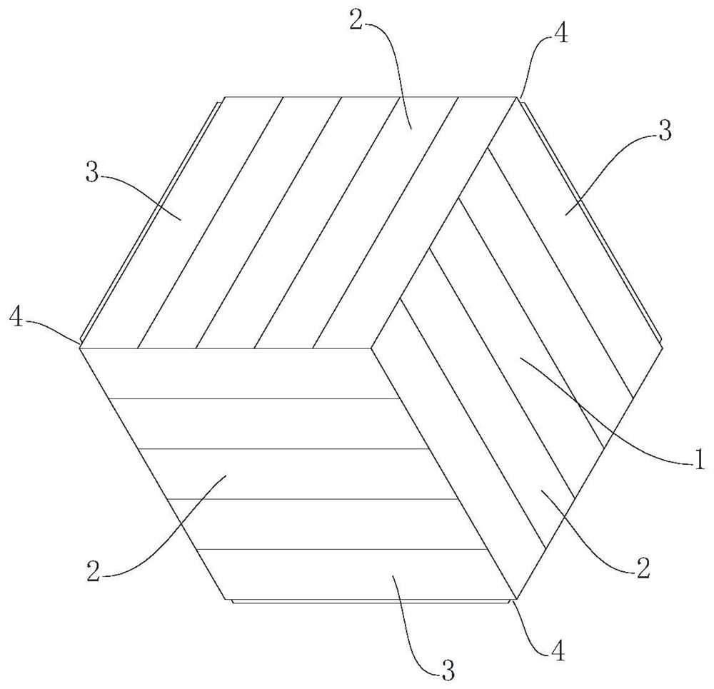
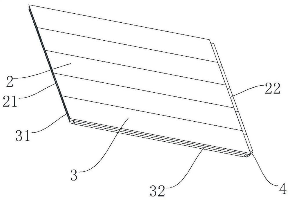
[0032] Such as Figure 1-6 As shown, the spliced ​​floor combination includes three diamond-shaped splicing panels 1 with the same structure that are spliced ​​with each other in a hexagonal shape. B3 structure, the floor strips B3 are located at the edges of three diamond-shaped splicing panels 1, and the splicing corners of the floor strips B3 are provided with cut corners 4 . The long side of floor bar A2 is 5 times of the short side of floor bar A2, and the long side of floor bar B3 is 5 times of the short side of floor bar B3, in the present embodiment, select the long side of floor bar A2 and floor bar B3 The sides are 550mm, and the short sides of the floorboards A2 and B3 are 110mm.

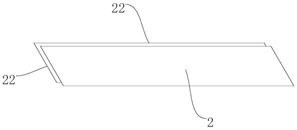
[0033] One long side and one short side of the floor strip A2 are provided with a groove A21, the other side long side and the other short side of the floor strip A2 are provided with a tenon A22, and the short side where the groove A21 is located The angle between the side and the long...

Embodiment 2

[0041] Such as Figure 7-12 As shown, the spliced ​​floor combination includes three diamond-shaped splicing panels 1 with the same structure that are spliced ​​with each other in a hexagonal shape. B3 structure, the floor strips B3 are located at the edges of three diamond-shaped splicing panels 1, and the splicing corners of the floor strips B3 are provided with cut corners 4 . The long side of floor bar A2 is 5 times of the short side of floor bar A2, and the long side of floor bar B3 is 5 times of the short side of floor bar B3, in the present embodiment, select the long side of floor bar A2 and floor bar B3 The sides are 550mm, and the short sides of the floorboards A2 and B3 are 110mm.

[0042] One long side and one short side of the floor strip A2 are provided with a groove A21, the other side long side and the other short side of the floor strip A2 are provided with a tenon A22, and the short side where the groove A21 is located The angle between the side and the lon...


PUM


Abstract

The invention discloses a spliced floor combination. The spliced floor combination comprises three rhombic spliced plates (1) which are spliced to form a hexagon and are of the same structure, each rhombic spliced plate (1) is composed of at least one floor strip A (2) and at least one floor strip B (3), the floor strips A (2) and the floor strips B (3) are parallelogram-shaped, and the floor strips B (3) are located at the edges of the three rhombic spliced plates (1); and cut corners (4) are arranged at the splicing corners of the floor strips B (3). The spliced floor combination not only has the characteristics of convenient and stable splicing and unique pattern, but also has the characteristics of material saving and cost reduction.

Description

technical field [0001] The invention relates to a spliced ​​floor, especially a spliced ​​floor combination. Background technique [0002] Flooring is an essential decoration in home life, providing decoration and protection for indoor and outdoor floors. Existing floors can be divided into solid wood floors, composite floors, bamboo floors, metal floors, etc. according to their materials. Generally, single floors are combined by splicing to cover the entire floor. In order to ensure the convenience of floor splicing, generally, corresponding tenons and grooves are provided on the floor, and splicing is performed by mating the tenons and grooves. However, the existing floors that use tenons and grooves for splicing are usually spliced ​​with rectangular or 45-degree floor strips. The splicing form of rectangular floor strips is relatively simple, the splicing pattern is relatively monotonous, and the aesthetics are insufficient, and the splicing is stable. Poor durability,...

Claims


Application Information

Patent Timeline
Patent Type & Authority Applications(China)
IPC IPC(8): E04F15/02E04F15/04
CPCE04F15/02E04F15/02038E04F15/048E04F2201/023E04F2201/043E04F2203/02
Inventor 顾国华
Owner 浙江上臣家居科技有限公司
Learn More