
Locking and separating mechanism capable of realizing multi-satellite sequential release and working method thereof

A separation mechanism and sequence technology, applied in the aerospace field, can solve problems such as impact damage to microsatellites, space environment pollution, etc., and achieve the effect of reducing the possibility of lateral shear damage to satellites, compact layout, and small installation space

Active Publication Date: 2021-01-12
HARBIN INST OF TECH
View PDF13 Cites 1 Cited by
  • Summary
  • Abstract
  • Description
  • Claims
  • Application Information

AI Technical Summary

Problems solved by technology

Traditional satellite locking and separating mechanisms mostly use pyrotechnic mechanisms. The huge impact force generated by pyrotechnic mechanisms such as the release of explosive bolts will cause huge impact damage to tiny satellites. At the same time, pyrotechnic products put forward relatively high requirements for the storage environment. , and will cause pollution of the space environment
Especially in recent years, with the gradual development of the multi-satellite launch method in the aerospace field, the traditional satellite locking and separating mechanism is no longer applicable, so it is necessary to design a locking and separating mechanism suitable for multiple satellites

Method used


Image

  • Locking and separating mechanism capable of realizing multi-satellite sequential release and working method thereof
  • Locking and separating mechanism capable of realizing multi-satellite sequential release and working method thereof
  • Locking and separating mechanism capable of realizing multi-satellite sequential release and working method thereof

Examples


Embodiment Construction

[0040] It should be noted that, in the case of no conflict, the embodiments of the present invention and the features in the embodiments can be combined with each other.

[0041] The present invention will be described in detail below with reference to the accompanying drawings and examples.

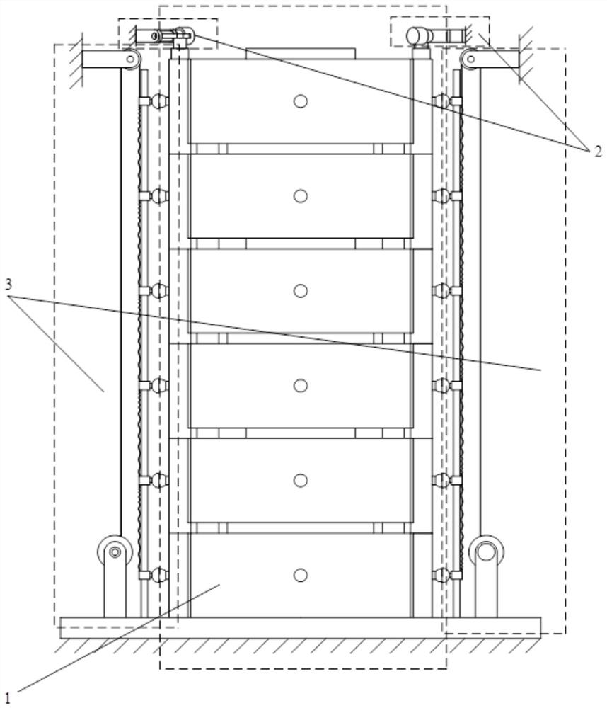
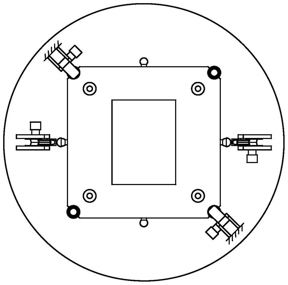
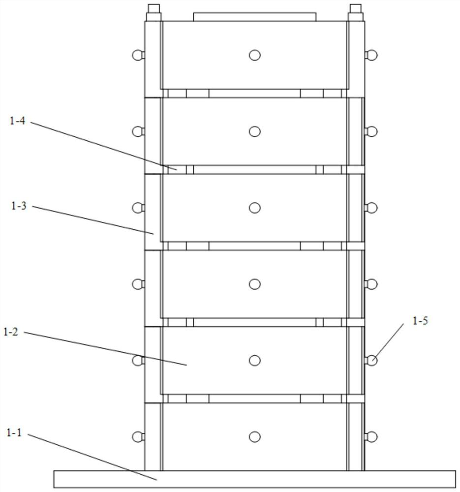
[0042] Such as Figure 1-Figure 7As shown, a locking and separating mechanism that can realize multi-satellite sequential release includes a satellite group 1, a locking assembly 2 and a separating assembly 3. The satellite group 1 includes several satellite bodies 1-2, and the locking assembly 2 is located above the satellite group 1, the locking assembly 2 is connected to the base, the locking assembly 2 has two groups, and is symmetrically arranged at the diagonal of the satellite group 1, and the separation assembly 3 Set up two groups, symmetrically arranged on the opposite sides of the satellite group 1, and the bottom of the separation component 3 is fixedly connected to the base...


PUM


Abstract

The invention provides a locking and separating mechanism capable of realizing multi-satellite sequential release and a working method thereof, the locking and separating mechanism comprises a satellite group, locking assemblies and a separating assembly, the satellite group comprises a plurality of satellite bodies, the locking assemblies are located above the satellite group, the locking assemblies are connected with a base, the number of the locking assemblies is two, wherein the two separation assemblies are symmetrically arranged at diagonal lines of the satellite group, the two separation assemblies are symmetrically arranged at two opposite sides of the satellite group, the bottoms of the separation assemblies are fixedly connected with the base, and the inner sides of the separation assemblies are connected with a satellite; the separation assembly comprises a sliding rail, a plurality of sliding blocks, a redundant steel wire rope, a fixed pulley A, a pulley support A, a fixedpulley B, a separation motor and a pulley support B; the multiple sliding blocks are matched with the sliding rails and correspond to the spherical structures on the satellite body in a one-to-one mode, the locking assembly tightly presses the satellite set, and the separation assembly separates the satellite bodies one by one. The satellite separating mechanism is simple in structure, low in energy consumption, convenient to install and store and capable of separating multiple satellites one by one.

Description

technical field [0001] The invention belongs to the field of aerospace technology, and in particular relates to a locking and separating mechanism capable of realizing multi-star sequential release and a working method thereof. Background technique [0002] In recent years, with the development of micro-nano technology, integrated and comprehensive electronic technology, and the innovation of satellite design ideas, the miniaturization of satellites has become an inevitable trend in the development of satellites in the future. When the new cube satellite carries a certain load, its mass and volume are smaller than those of other shapes. Traditional satellite locking and separating mechanisms mostly use pyrotechnic mechanisms. The huge impact force generated by pyrotechnic mechanisms such as the release of explosive bolts will cause huge impact damage to tiny satellites. At the same time, pyrotechnic products put forward relatively high requirements for the storage environmen...

Claims


Application Information

Patent Timeline
IPC IPC(8): B64G1/64B64G1/10
CPCB64G1/645B64G1/10B64G1/641B64G1/002B64G1/222
Inventor 岳洪浩杨飞李怀宇陆一凡
Owner HARBIN INST OF TECH
Learn More