
Organic light-emitting diode display protection device

A technology of light-emitting diodes and protection devices, which is applied in the direction of supporting machines, mechanical equipment, machines/supports, etc., to achieve the effect of long service life

Pending Publication Date: 2021-01-12
JIANGSU SAIBO YUHUA TECH CO LTD
View PDF0 Cites 0 Cited by
  • Summary
  • Abstract
  • Description
  • Claims
  • Application Information

AI Technical Summary

Problems solved by technology

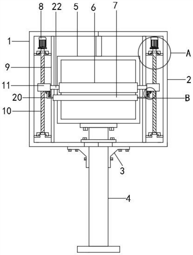
[0005] Therefore, the present invention provides a protection device for an organic light-emitting diode display. By setting the left bracket and the right bracket, the display can be protected from wind and rain, effectively increasing the service life of the display, and by setting the servo motor to drive the screw to rotate to drive the dust scraper. Dust cleaning is carried out on the surface of the display, which solves the above-mentioned deficiencies of the existing outdoor light-emitting diode displays

Method used


Image

  • Organic light-emitting diode display protection device
  • Organic light-emitting diode display protection device
  • Organic light-emitting diode display protection device

Examples


Embodiment 1

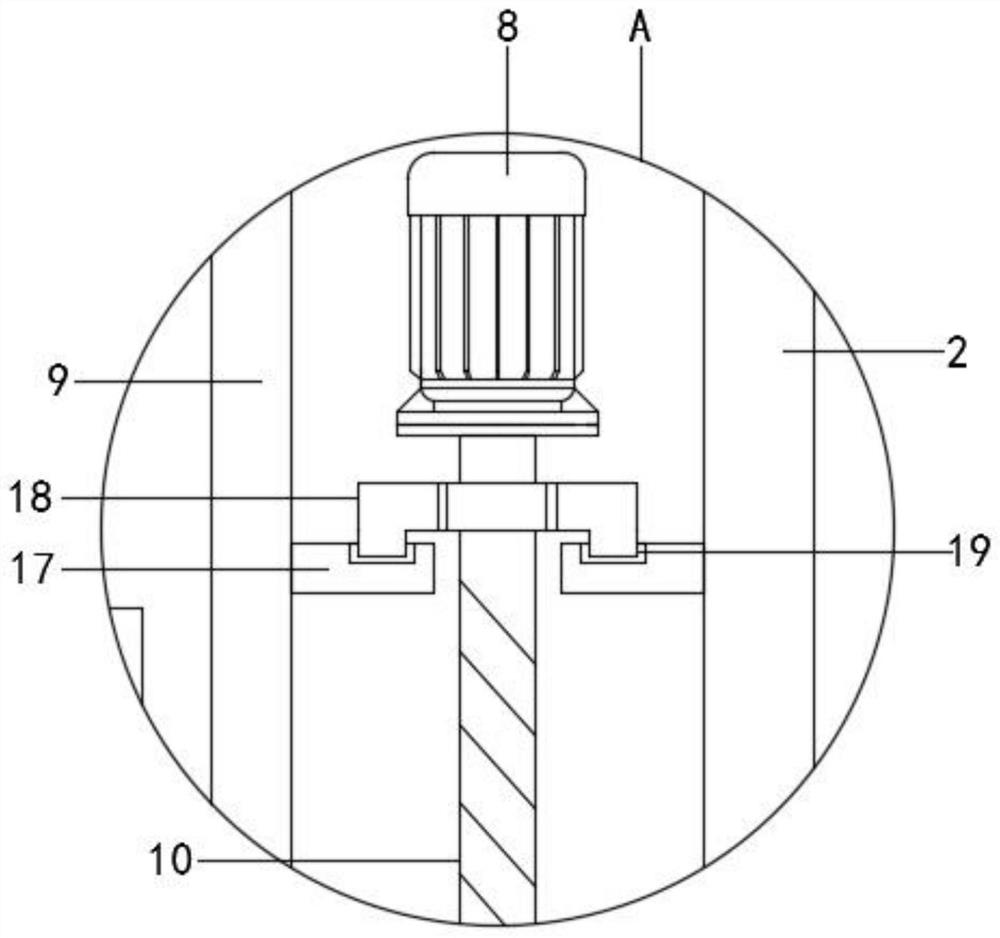
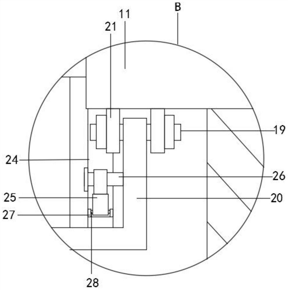
[0028] Refer to the attached Figure 1-6 , a protective device for an organic light emitting diode display in this embodiment, comprising a display 5, the display 5 is fixedly connected to the support column 4 by bolts, the outer wall of the middle part of the support column 4 is inserted into the left fixing ring 15, and the middle part of the support column 4 The outer wall is plugged with the right fixed ring 16, the left end of the left fixed ring 15 is fixedly connected to the left bracket 1, the right end of the right fixed ring 16 is fixedly connected to the right bracket 2, and the inner walls of the left bracket 1 and the right bracket 2 are fixedly installed with a vertical support plate 9 , the outer wall of the vertical support plate 9 is fixedly installed with a horizontal support plate 17, the inner wall of the left bracket 1 and the right bracket 2 is fixedly installed with a horizontal support plate 17, the horizontal support plate 17 is provided with a chute 19...

Embodiment 2

[0037] Refer to the attached Figure 7 , the difference from Example 1 is: the tops of the left bracket 1 and the right bracket 2 are set as curved surfaces;

[0038] The specific implementation scenarios are:

[0039] Compared with Embodiment 1, when using the present invention, when the display 5 has more dust and stains, the electric telescopic rod 2 30 elongates and drives the push plate 29 to move outward, and the push plate 29 drives the slide block 18 to move outward on the horizontal support plate. Slide 17 until the dust-scraping board 6 exceeds the display 5, the slide block 18 drives the servo motor 8, the screw mandrel 10 and the drive block 11 to move outward together, and the extension of the electric telescopic rod 1 25 drives the rotation of the L-shaped rod 2 20 to make the vacuum cleaner 7 and the dust scraping plate 6 are on the same horizontal plane, so that the servo motor 8 works, the output end of the servo motor 8 drives the screw rod 10 to rotate, and...


PUM


Abstract

The invention discloses an organic light-emitting diode display protection device. According to the technical scheme, the device comprises a display, wherein the display is fixedly connected with a supporting column through bolts, a left fixing ring is inserted into the outer wall of the middle of the supporting column, a right fixing ring is inserted into the outer wall of the middle of the supporting column, the left end of the left fixing ring is fixedly connected with a left support,the right end of the right fixing ring is fixedly connected with a right support, and vertical supporting plates are fixedly installed on the inner walls of the left support and the right support. According to the device, lead screws drive driving blocks to move up and down, so that the driving blocks moveup and down more stably, a dust scraping plate and a dust collector move up and down more stably, and dust on the surface of the display is automatically removed; the removed dust is sucked by the dust collector, so that the dust cannot enter the display, and the display is effectively protected; and the left support and the right support effectively protect the display against wind and rain, so that the service life of the display is longer.

Description

technical field [0001] The invention relates to the technical field of diode displays, in particular to an organic light emitting diode display protection device. Background technique [0002] Light-emitting diode display is a display using light-emitting diodes, also known as "light-emitting diode display board", which is widely used in information release, outdoor media, stadiums, indoor large-scale display solutions, in addition, in outdoor traffic instructions or public transportation It is also very common in display boards. The common monitors are computer and TV screens. The screen size is calculated according to the diagonal of the screen, usually in inches (inch). Currently, the mainstream sizes are 17", 19", and 21" ", 22", 24, 27", etc. refer to the diagonal length of the screen. Commonly used displays include standard screen (narrow screen) and wide screen, and the aspect ratio of the square screen is 4:3 (and A small proportion is 5:4), and the aspect ratio of ...

Claims


Application Information

Patent Timeline
Patent Type & Authority Applications(China)
IPC IPC(8): B08B1/00B08B5/04B08B13/00B08B15/04F16M11/04
CPCB08B5/04B08B13/00B08B15/04F16M11/04B08B1/165B08B1/30B08B1/12
Inventor 肖建军
Owner JIANGSU SAIBO YUHUA TECH CO LTD
Learn More