Oil consuming system

An oil consumption and fuel tank technology, applied in clutches, friction clutches, belts/chains/gears, etc., can solve problems such as short residence time, short oil circulation time, and inability to discharge free air, achieve rapid degassing and reduce structure space, the effect of reducing the flow cross section

Pending Publication Date: 2021-01-08
MAGNA POWERTRAIN AG & CO KG
View PDF10 Cites 0 Cited by
  • Summary
  • Abstract
  • Description
  • Claims
  • Application Information

AI Technical Summary

Problems solved by technology

[0003] Usually caused by the problem that the oil circulation time in the oil consumption system is very short
This means that the average residence time of the oil in the storage container is too short to escape the free air additionally absorbed in the oil

Method used


Image

  • Oil consuming system

Examples


Embodiment Construction

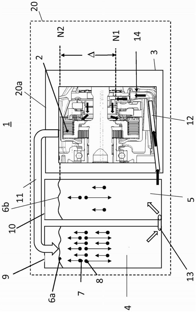
[0018] This is a wet multi-disc clutch, which is supplied with oil via the oil supply 12 . Oil is fed into the disc carrier of the clutch via suitable oil supply bores 14 , which are indicated by arrows in the figure.

[0019] By the rotation of the clutch, oil is thrown out at the highest point of the clutch and delivered to the oil return portion 11 . Oil guides can also be used here, as are already known. In this case, the oil guide is shown schematically in the drawing and can represent a return line conducted in the housing 20 a or a separate return line which is also arranged outside the housing 20 a. The oil return line 11 leads into the first oil tank 4 in which the air-oil mixture is deposited. As shown in the figure, the air 7 is separated from the oil droplets 8 . The rising air 7 escapes via the first exhaust mechanism 9 . In this case, an oil level 6 a is formed in the first oil tank. The first oil tank 4 is connected to the second oil tank 5 via a connecting...


PUM


Abstract

The invention relates to an oil consuming system, and the system comprises at least one rotary component and at least one oil supply flow from an oil reservoir, the oil consuming system having an oilreturn flow to a first reservoir and an oil supply flow via at least one second reservoir.

Description

technical field [0001] The invention relates to an oil consumption system having at least one rotating part and at least one oil supply from an oil tank. Background technique [0002] Oil is an important component in many oil consuming systems, such as clutch systems. The oil is used for cooling and lubrication. Several operating characteristics of the clutch system are directly related to the material parameters of the oil. Thus, inter alia oil density, temperature-dependent viscosity, compatibility of the oil with different materials of the system, air separation capacity and oil properties which are important for the tendency to form foam. [0003] The problem often arises that the oil circulation time in the oil consuming system is very short. This means that the average residence time of the oil in the storage container is too short to escape the free air that is additionally absorbed in the oil. This high proportion of undissolved air can cause the oil to foam. If...

Claims


Application Information

Patent Timeline
Patent Type & Authority Applications(China)
IPC IPC(8): F16D13/72F16D13/74
CPCF16D13/52F16D13/72F16D13/74F16D2300/06F16H57/0473F16D2048/0218
Inventor 约阿希姆·克卢格克里斯托夫·克伦
Owner MAGNA POWERTRAIN AG & CO KG
Why Eureka
Try Eureka