


Quick Research
Generate reliable direction feasibility study reports for your R&D in just a few steps.

Technical Q&A
Discover and master advanced knowledge NOW. Basics, ideas, possibilities, all at once.

Find Solutions
As an expert in R&D theories, this can generate solutions to your technical problems instantly.

Evaluate Feasibility
Analyze your overall solution with one click, know your potential R&D risks in advance.

Monitor Landscape
Get weekly tech updates, stay abreast of the latest tech innovations and key insights.
Construction reinforcing mesh welding device
A technology for welding devices and building steel bars, which is applied to auxiliary devices, welding equipment, auxiliary welding equipment, etc., can solve the problems of manually pushing the safety of steel mesh sheets manually, and achieve the effect of being easy to remove and improving work efficiency.
- Summary
- Abstract
- Description
- Claims
- Application Information
AI Technical Summary
Problems solved by technology
Method used
Image


Examples
Embodiment 1
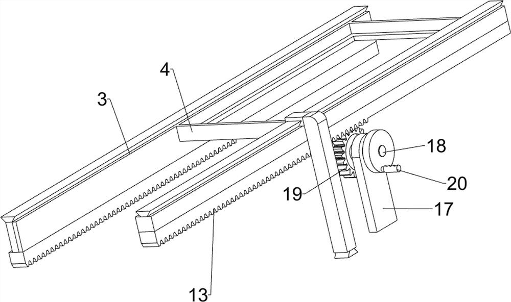
[0025] A construction reinforcement mesh welding device, such as Figure 1-5 As shown, it includes a base plate 1, a support frame 2, a sliding frame 3, a placement frame 4, a feeding mechanism 5 and a pushing mechanism 6, and the left and right sides of the base plate 1 are symmetrically arranged with a support frame 2 in a sliding manner. The supporting frame 2 is equipped with a sliding frame 3 in a sliding manner, and a placement frame 4 is arranged between the sliding frames 3. The top of the base plate 1 is provided with a feeding mechanism 5, and the top of the base plate 1 is provided with a pushing mechanism 6.
[0026] When people need to use this device, first people place the steel mesh sheet to be welded on the placement frame 4, and then start the feeding mechanism 5, so that the feeding mechanism 5 operates to weld the steel mesh sheet, and at the same time the feeding mechanism 5 drives to push The mechanism 6 operates, and the pushing mechanism 6 operates to d...
Embodiment 2
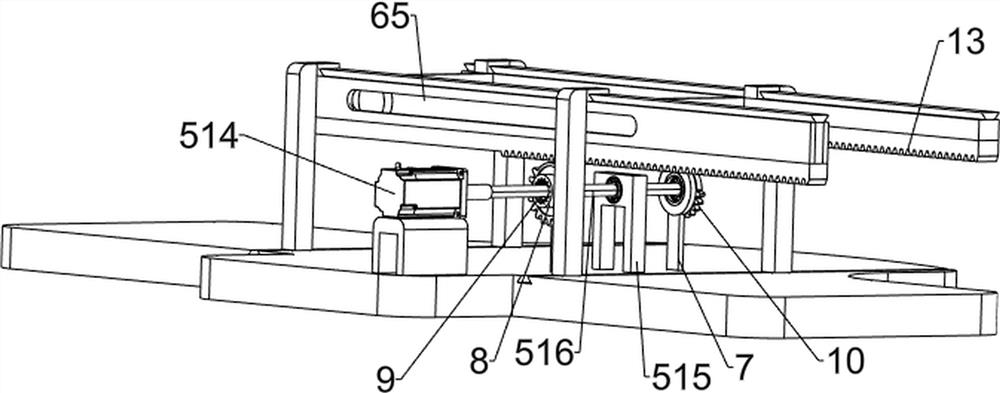
[0032] On the basis of Example 1, such as Figure 4-7 As shown, it also includes a third bearing seat 7, a shaft sleeve 8, a second missing gear 10, a pawl 11, an elastic member 12, a second rack 13, a fourth bearing seat 14, a second rotating shaft 15 and a third circle Gear 16, base plate 1 top right side front and rear symmetrically fixedly connected with the 3rd bearing seat 7, on the 3rd bearing seat 7 all is provided with the axle sleeve 8 with the rotation type, all has ratchet groove 9 on the axle sleeve 8, the axle sleeve 8 is connected with the rotating rod 516 in a rotational manner, the shaft sleeve 8 is provided with a second gear 10, and the rotating rod 516 is provided with two ratchets 11, the ratchets 11 are matched with the shaft sleeve 8, and the ratchets 11 are connected with the rotating shaft. An elastic member 12 is arranged between the rods 516, and the elastic member 12 is a torsion spring. The bottom of the sliding frame 3 is provided with a second ra...
PUM
 Abstract
Description
Claims
Application Information
 - R&D Engineer
- R&D Manager
- IP Professional
- Industry Leading Data Capabilities
- Powerful AI technology
- Patent DNA Extraction
Browse by: Latest US Patents, China's latest patents, Technical Efficacy Thesaurus, Application Domain, Technology Topic, Popular Technical Reports.
© 2024 PatSnap. All rights reserved.Legal|Privacy policy|Modern Slavery Act Transparency Statement|Sitemap|About US| Contact US: help@patsnap.com