Variable-frequency motor and frequency converter combined device

A combined device and variable frequency motor technology, which is applied in the direction of electromechanical devices, electric components, cooling/ventilation devices, etc., can solve the problems of heat flow and heat dissipation effect to be improved, so as to increase air volume, improve convection heat dissipation effect, and accelerate conduction and dissipation Effect

Pending Publication Date: 2021-01-05
无锡市明通动力工业有限公司
View PDF0 Cites 0 Cited by
  • Summary
  • Abstract
  • Description
  • Claims
  • Application Information

AI Technical Summary

Problems solved by technology

In the existing frequency conversion motor and frequency converter combination device, heat dissipation fins are arranged on the bottom side of the frequency converter, and the heat dissipation fins are formed by the fan impeller located at the end of the motor shaft and the fan cover installed on the end surface of the motor surrounding it. In the cooling airflow flowing along the outer surface of the motor, the bottom surface of the inverter housing and the heat dissipation fins arranged there also experience the cooling airflow, so that a fan can simultaneously dissipate heat to the inverter motor and the inverter. However, due to the close distance between the variable frequency motor and the frequency converter, the heat is easy to flow between the two, and the heat dissipation effect needs to be improved.

Method used


Image

  • Variable-frequency motor and frequency converter combined device
  • Variable-frequency motor and frequency converter combined device
  • Variable-frequency motor and frequency converter combined device

Examples


Embodiment Construction

[0034] The technical solutions in the embodiments of the present invention will be clearly and completely described below in conjunction with the drawings in the present invention. Apparently, the described embodiments are only some of the embodiments of the present invention, not all of them. Based on the embodiments of the present invention, all other embodiments obtained by persons of ordinary skill in the art without making creative efforts belong to the protection scope of the present invention.

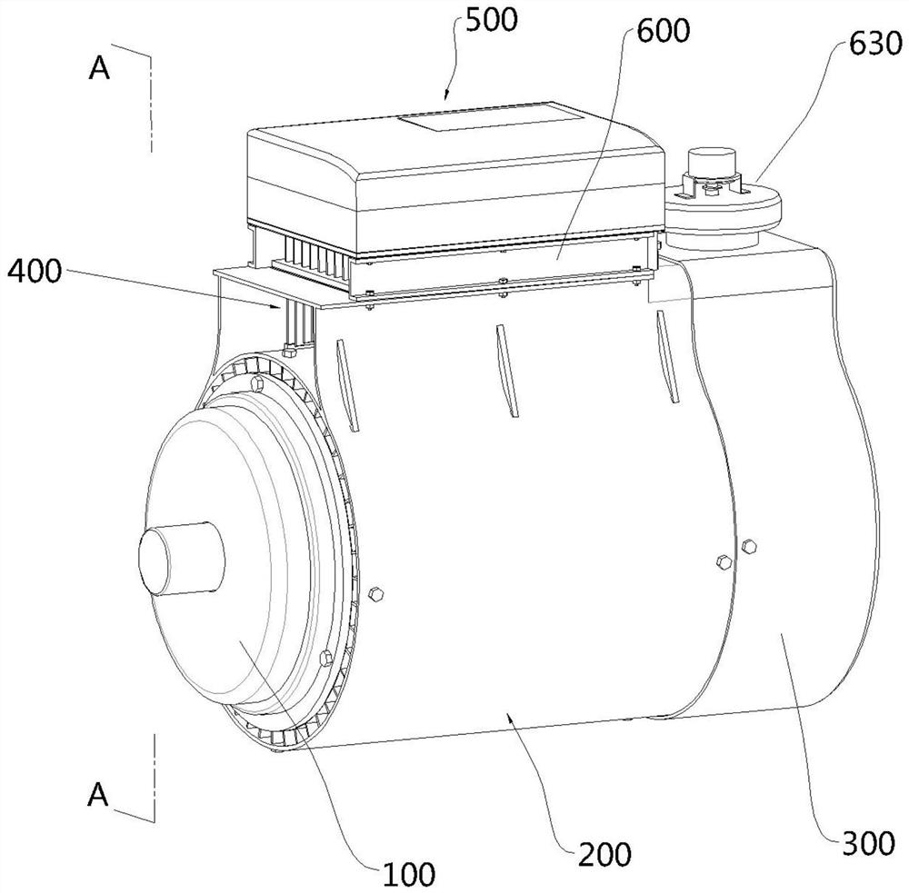
[0035] Such as figure 1 The combination device of a variable frequency motor and a frequency converter shown includes a motor 100, a housing 200 sleeved on the motor 100, a wind guide cover 300 disposed at the tail end of the motor 100, a cooling assembly 400, and a frequency conversion device mounted on the motor 100. The device 500 and the air supply assembly 600; the cooling assembly 400 and the air supply assembly 600 can effectively cool down the motor 100 and the frequency...


PUM


Abstract

The invention discloses a variable frequency motor and frequency converter combined device, and belongs to the technical field of variable frequency motors. The invention mainly comprises a motor, a shell, an air guide cover, a refrigeration assembly, an air supply assembly and a frequency converter; the shell comprises a barrel and a frame, the air guide cover is similar to an air multiplier in structure and comprises an inner ring body, an outer ring body, an air cavity and a crack, and the refrigeration assembly comprises a placement frame, a semiconductor chilling plate and a heat dissipation piece abutting against the hot end of the semiconductor chilling plate and placed in the frame body. The frequency converter comprises a bottom plate, a box body, a top cover, a driving plate anda capacitor plate, the driving plate and the capacitor plate are installed below the box body and abut against the bottom plate, the bottom plate is provided with fins and a contact plate, and the contact plate abuts against the cold end face of the semiconductor chilling plate. The air supply assembly comprises a side plate arranged on the outer side of the fin, a necking fan cover and an air compressor, and the air compressor is communicated with the necking fan cover and the air cavity. According to the variable frequency motor and frequency converter combined device, the heat dissipation effect is effectively improved.

Description

technical field [0001] The invention relates to the technical field of frequency conversion motors, in particular to a combination device of frequency conversion motors and frequency converters. Background technique [0002] The variable frequency motor and the frequency converter are independent components. Due to the high heat generation, the frequency converter and the frequency conversion motor need their own fans for heat dissipation. In the existing frequency conversion motor and frequency converter combination device, heat dissipation fins are arranged on the bottom side of the frequency converter, and the heat dissipation fins are formed by the fan impeller located at the end of the motor shaft and the fan cover installed on the end surface of the motor surrounding it. In the cooling airflow flowing along the outer surface of the motor, the bottom surface of the inverter housing and the heat dissipation fins arranged there also experience the cooling airflow, so that...

Claims


Application Information

Patent Timeline
Patent Type & Authority Applications(China)
IPC IPC(8): H02K5/20H02K5/18H02K9/04H02K11/00
CPCH02K5/18H02K5/20H02K9/04H02K11/0094
Inventor 濮晓明吴放明唐晓强
Owner 无锡市明通动力工业有限公司
Why Eureka
Try Eureka