A self-ventilating water bath constant temperature oscillator
A technology of constant temperature oscillator and water bath, which is applied in biochemical instruments, bioreactor/fermenter combination, specific-purpose bioreactor/fermenter, etc. It can solve the problems of increasing equipment power consumption, difficulty in achieving constant temperature in water bath, and unfavorable microorganisms. Or the normal growth of cell tissue and other problems, to achieve the effect of reducing power consumption, reducing evaporation consumption, and avoiding pollution
- Summary
- Abstract
- Description
- Claims
- Application Information
AI Technical Summary
Problems solved by technology
Method used
Image
Examples
Embodiment 1
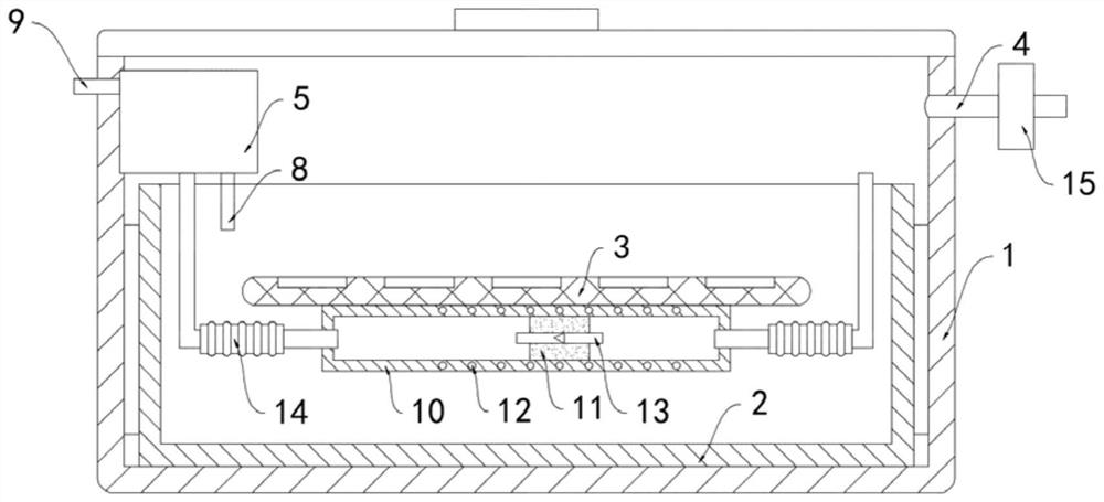
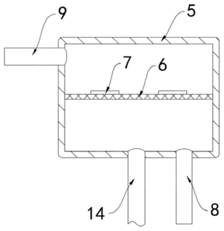
[0021] like Figure 1-2 As shown, a self-ventilating water bath constant temperature oscillator includes a box body 1, a water bath 2 is arranged in the box body 1, an oscillation plate 3 is arranged in the water bath 2, and the upper surface of the oscillation plate 3 is provided with a plurality of etc. The placement grooves arranged away from the array are convenient for the placement of the petri dishes. The bottom of the oscillation plate 3 is equipped with a driving mechanism for driving the oscillation plate 3 to move back and forth. The driving mechanism is in the prior art and will not be repeated here. There is an air intake pipe 4 on the wall, and a filter 15 is installed at the air intake end of the air intake pipe 4 to filter out the bacteria and microorganisms in the air entering the air intake pipe 4, so as to avoid pollution to the cultivation of microorganisms or cell tissues. The inner side wall of 1 is fixedly connected with a condensation box 5, a condensed...
Embodiment 2
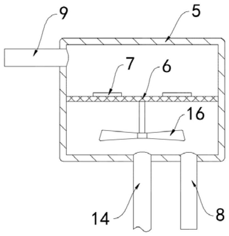
[0026] like image 3 As shown, the difference between this embodiment and Embodiment 1 is: the condensate mesh plate 6 is rotatably connected with the inner side wall of the condensation box 5, and the lower surface of the condensate mesh plate 6 is coaxially fixedly connected with a fan 16 through the rotating shaft. 16 is provided at the upper port of the communication pipe 13 .
[0027] In this embodiment, when the airflow blows to the fan 16, the fan 16 is driven to rotate, and the condensate screen 6 rotates synchronously with the fan 16. Under the action of centrifugal force, the water droplets condensed on the surface of the condensate screen 6 are thrown to the surrounding condensation boxes. On the inner wall of 5, the water droplets quickly fall along the inner wall of the condensing box 5 and collect to the return pipe 8, so as to avoid the accumulation of water droplets on the condensate screen plate 6 and hinder the air flow exchange.
PUM
 Abstract
Description
Claims
Application Information
 - R&D
- Intellectual Property
- Life Sciences
- Materials
- Tech Scout
- Unparalleled Data Quality
- Higher Quality Content
- 60% Fewer Hallucinations
Browse by: Latest US Patents, China's latest patents, Technical Efficacy Thesaurus, Application Domain, Technology Topic, Popular Technical Reports.
© 2025 PatSnap. All rights reserved.Legal|Privacy policy|Modern Slavery Act Transparency Statement|Sitemap|About US| Contact US: help@patsnap.com


