
Method for controlling esc integrated braking system

A brake system and brake technology, applied in the direction of brake safety systems, brakes, brake components, etc., can solve the problems of reducing the viscosity of brake fluid, increasing low-temperature fluidity, and reducing braking performance, so as to improve the pedal feel, Improves responsiveness and secures braking force

Active Publication Date: 2021-01-05
HYUNDAI MOBIS CO LTD
View PDF8 Cites 2 Cited by
  • Summary
  • Abstract
  • Description
  • Claims
  • Application Information

AI Technical Summary

Problems solved by technology

[0003]However, in the brake system using brake fluid, such as ESC integrated brake system, because the viscosity of the brake fluid increases at low temperature, the time delay (increase low temperature fluidity) until the pressure developed in the master cylinder is transmitted to the wheel through the perforated inlet valve (a small hole for injecting fluid), causing a slippery feeling
[0004] In this regard, various methods have been developed to solve the above-mentioned problems that occur at low temperatures, but with slight pressure on the vehicle before braking, or by using regenerative In the case of braking or motor braking, since the brake fluid is kept at a low temperature, the braking performance decreases during emergency braking or immediately before stopping without regenerative braking force, and the safety of the driver cannot be guaranteed.
[0005] Also, the method of adding a heating wire to the hydraulic pipe has the effect of reducing the viscosity of the brake fluid, but it has a problem of requiring additional parts to increase the cost
In addition, the method of compensating for viscosity by applying DC current to the motor to heat the motor when the driver has no steering intention is not applicable when the driver has the steering intention, thus reducing the viscosity of the brake fluid due to the lack of continuity to generate heat limited
In addition, the method of raising the temperature of the actuator by setting the target pressure higher while the vehicle is stopped has the problem that it is impossible to generate heat while the vehicle is running.

Method used

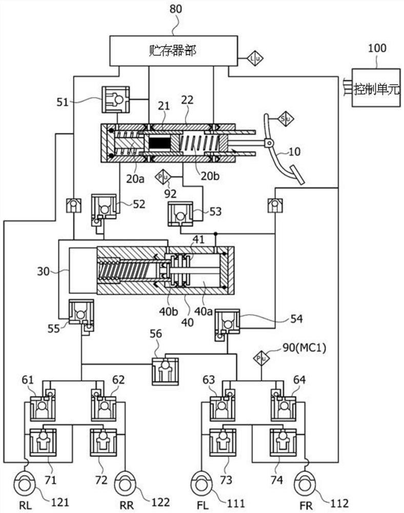
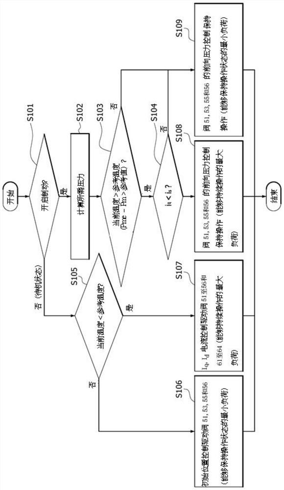
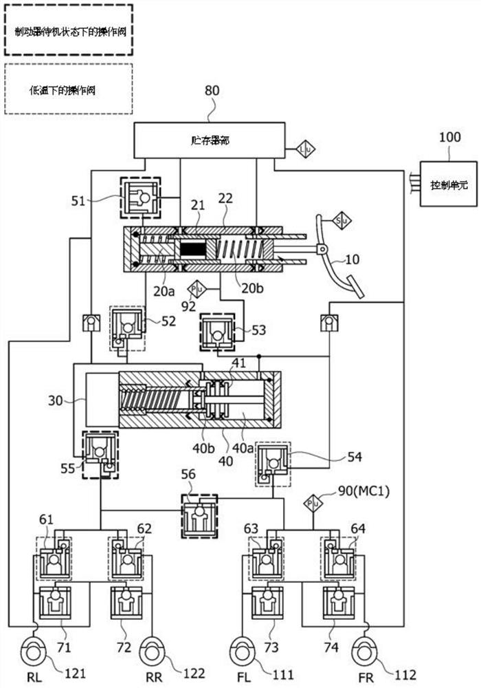

Image

  • Method for controlling esc integrated braking system
  • Method for controlling esc integrated braking system
  • Method for controlling esc integrated braking system

Examples


Embodiment Construction

[0029] As is conventional in the respective fields, some exemplary embodiments may be shown in the drawings in terms of functional blocks, units and / or modules. Those of ordinary skill in the art will understand that these blocks, units and / or modules are physically implemented by electronic (or optical) circuitry such as logic circuits, discrete components, processors, hardwired circuits, memory elements, wiring connections, and the like. When the blocks, units and / or modules are implemented by processors or similar hardware, they can be programmed and controlled using software (eg, code) to perform the various functions discussed herein. Alternatively, each block, unit and / or module may be implemented by dedicated hardware or as a combination of dedicated hardware performing some functions and a processor (e.g., one or more programmed processors and associated circuits) performing other functions. combination. Each block, unit and / or module of some exemplary embodiments may...


PUM


Abstract

The present invention provides a method for controlling an ESC integrated braking system including: checking, by a control unit, whether a brake is in an on state or a standby state as the braking system is activated; checking, by the control unit, whether a current temperature value is in a low temperature state lower than specified reference temperature; and controlling, by the control unit, a current duty for driving a hydraulic control valve and a current component of a motor for driving a master cylinder according to the state of the brake and whether the current temperature value is in the low temperature state.

Description

technical field [0001] Exemplary embodiments of the present disclosure relate to a method for controlling an ESC integrated braking system, and more particularly, to a method for controlling an ESC integrated braking system, which improves actuator performance at low temperatures. The temperature of the brake fluid is reduced to reduce the viscosity of the brake fluid, thereby improving the response of the brakes to ensure the braking force of the driver when he has the intention to brake. Background technique [0002] Typically, the braking system includes: anti-lock brake system (anti-lockbrake system, ABS) to prevent wheel slip during braking, brake traction control system ( brake traction control system, BTCS), and a vehicle attitude control system (ESC: Electronic Stability Control System), etc., wherein the vehicle attitude control system stabilizes the The driving status of the vehicle. [0003] However, in a brake system using brake fluid, such as an ESC integrated...

Claims


Application Information

Patent Timeline
Patent Type & Authority Applications(China)
IPC IPC(8): B60T13/74B60T17/22
CPCB60T13/74B60T17/22B60T8/1755B60T2220/04B60T8/171B60T7/042B60T13/686B60T13/745B60T8/32B60T8/172B60T17/221B60Y2400/81B60T7/06
Inventor 薛镛哲
Owner HYUNDAI MOBIS CO LTD
Learn More