Cardiopulmonary coupling auxiliary respirator

An auxiliary respirator, cardiopulmonary coupling technology, applied in respirator, chemical instruments and methods, dispersed particle filtration, etc., can solve the problems of single function, inconvenient operation, cumbersome operation, etc., to simplify operation steps, reduce occupied space, The effect of improving the quality of breathing

Inactive Publication Date: 2021-01-05
HUNAN VENTMED MEDICAL TECH CO LTD
View PDF13 Cites 1 Cited by
  • Summary
  • Abstract
  • Description
  • Claims
  • Application Information

AI Technical Summary

Problems solved by technology

[0003] At present, when the ventilator is used as an auxiliary device in the field of cardiopulmonary coupling, it is mostly a separate device. The use of two devices together takes up a lot of space and is inconvenient to operate. Moreover, the quality of air inhaled by the user during cardiopulmonary coupling monitoring affects the monitoring effect of the device.
The function of the existing ventilator is single, and the disinfection of the parts that are in direct contact with the mouth needs to be used in conjunction with other disinfection equipment, which is inconvenient to use
[0004] Patent Publication No. CN209187808U provides a ventilator dust-proof device and a ventilator, including a host and a gas pipeline. This patent only improves the function of the ventilator itself, but in actual use, the ventilator is mostly used to assist other equipment. Use, a single ventilator cannot be used conveniently and diversely
When the cardiopulmonary coupling monitoring equipment is in use, it sometimes needs the assistance of a ventilator. At that time, the two independent equipment have a large space and the operation is cumbersome and inconvenient to use.
[0005] The patent publication No. CN205612842U provides a filter for ventilator, including a shell, and the inner cavity of the first shell is equipped with an activated carbon filter layer. The patented device only uses one step of physical filtration for the inhaled air. , the air purification effect is not good, which affects the user's use effect

Method used


Image

  • Cardiopulmonary coupling auxiliary respirator
  • Cardiopulmonary coupling auxiliary respirator
  • Cardiopulmonary coupling auxiliary respirator

Examples


Embodiment

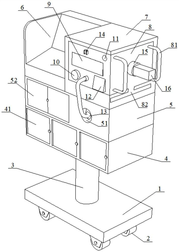
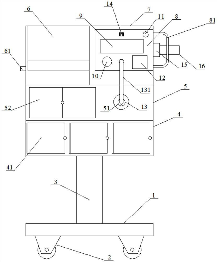
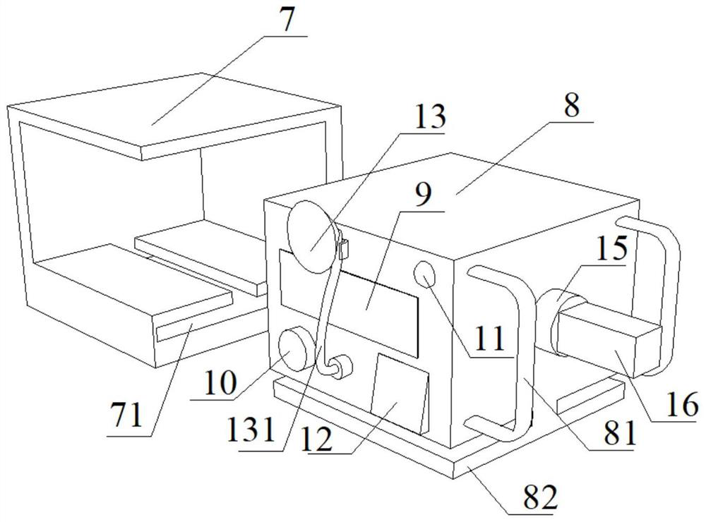
[0030] as attached figure 1 to attach image 3 As shown, the present invention provides a cardiopulmonary coupling assisted respirator, including a base 1, a storage box 4, an ultraviolet disinfection cabinet 5, a cardiopulmonary coupling device 6, a ventilator table 7, a ventilator 8, a breathing mask 13, and a filter tube 16; The upper side of the base 1 is provided with a storage box 4; the upper part of the storage box 4 is fixed with an ultraviolet disinfection cabinet 5; the left side of the upper part of the ultraviolet disinfection cabinet 5 is fixed with a cardiopulmonary coupling device 6; the cardiopulmonary coupling The right side of the device 6 is equipped with a ventilator table 7; the ventilator table 7 is slidably connected to a ventilator 8; the respiratory mask 13 is fixedly connected to the front of the ventilator 8; the right side of the ventilator 8 is provided with filter tube 16.

[0031] as attached figure 1 As shown, the lower part of the base 1 is...


PUM


Abstract

The invention provides a cardiopulmonary coupling auxiliary respirator, and belongs to the field of medical equipment. The cardiopulmonary coupling auxiliary respirator comprises a base, a storage box, an ultraviolet disinfection cabinet, cardiopulmonary coupling equipment, a ventilator table, a ventilator, a breathing mask and a filter tube. According to the cardiopulmonary coupling auxiliary respirator, the auxiliary ventilator and the cardiopulmonary coupling equipment are combined together for use through a sliding rail structure, the occupied space is reduced, the operation steps are simplified, and the working efficiency is improved; activated carbon and a UV lamp are arranged in the filter tube, so that air is subjected to dual efficient purification, and the breathing quality of auser is improved; and meanwhile, due to the arrangement of a special mask disinfection chamber and other disinfection chambers, cross infection is prevented from happening, and user health is prevented from being harmed.

Description

technical field [0001] The invention belongs to the field of medical equipment, in particular to a cardiopulmonary coupling auxiliary respirator. Background technique [0002] In modern clinical medicine, the ventilator, as an effective means of artificially replacing the spontaneous ventilation function, has been widely used in respiratory failure caused by various reasons, anesthesia respiratory management during major surgery, respiratory support treatment and emergency resuscitation. It occupies a very important position in the field of modern medicine. Ventilator is a vital medical equipment that can prevent and treat respiratory failure, reduce complications, save and prolong the life of patients. [0003] At present, when the ventilator is used as an auxiliary device in the field of cardiopulmonary coupling, it is mostly a separate device. The use of two devices together takes up a lot of space and is inconvenient to operate. Moreover, the quality of air inhaled by t...

Claims


Application Information

Patent Timeline
Patent Type & Authority Applications(China)
IPC IPC(8): A61M16/00A61L9/20A61M16/10B01D46/00B01D46/12B01D53/00B01D53/04B01D53/48B01D53/52B01D53/54B01D53/58B01D53/74
CPCA61M16/0003A61M16/0051A61L9/20A61M16/107B01D46/0036B01D46/12B01D53/04B01D53/74B01D53/007B01D53/58B01D53/52B01D53/485B01D53/54B01D2259/804B01D2259/4533
Inventor 吴超民袁再鑫粟锦平
Owner HUNAN VENTMED MEDICAL TECH CO LTD
Why Eureka
Try Eureka