
Tunnel boring machine cutterhead for assisting rock breaking through high-pressure water jet

A technology of high-pressure water jetting and tunneling, which is applied in tunnels, mining equipment, earthwork drilling and mining, etc. It can solve problems affecting the speed of tunneling and construction, damage and failure of key components, and high cost ratio of tools, so as to ensure the destructive power and damage The effect of reducing the scope, shortening the construction period, and ensuring the speed

Active Publication Date: 2021-01-01
STATE KEY LAB OF SHIELD & TUNNELING TECH +1
View PDF5 Cites 2 Cited by
  • Summary
  • Abstract
  • Description
  • Claims
  • Application Information

AI Technical Summary

Problems solved by technology

During the excavation process of the tunnel boring machine, the hob rubs against the rock and heats up, and the temperature can reach more than 300 degrees, which increases the wear of the hob and shortens its life. It needs to be replaced after about 300-500 meters, and the cost of the tool accounts for a relatively high proportion of the total cost.
The cutter head is subjected to high-intensity impact load during the excavation process, and the vibration is very severe, leading to premature damage and failure of key components, damage to the main bearing, shortened mechanical life, and rock cracks also seriously affect the excavation speed and construction speed. It is reported that it is the highest in my country. The monthly excavation has reached 1209.8 meters, and the efficiency is not very high

Method used


Image

  • Tunnel boring machine cutterhead for assisting rock breaking through high-pressure water jet
  • Tunnel boring machine cutterhead for assisting rock breaking through high-pressure water jet
  • Tunnel boring machine cutterhead for assisting rock breaking through high-pressure water jet

Examples


Embodiment

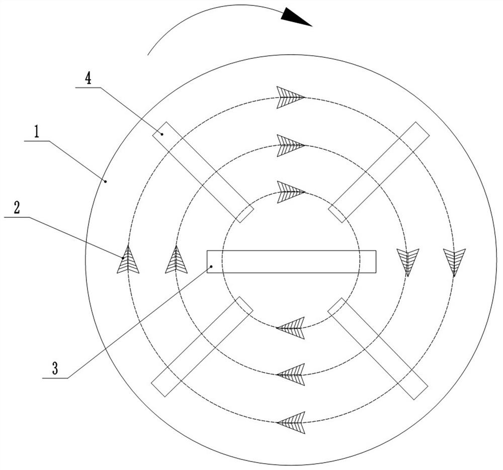
[0020] Such as Figure 1-Figure 4 As shown, the present invention provides a tunnel boring machine cutter head with high-pressure water jet assisting rock breaking, including a cutter head 1 body, a first hob assembly 3 arranged on the cutter head 1 body, a plurality of first hob The knife assembly 4 and a plurality of scrapers 2 ; the first hob assembly 3 and the first hob assembly 4 both include a rotating shaft 8 and a plurality of hobs 9 arranged on the rotating shaft 8 .

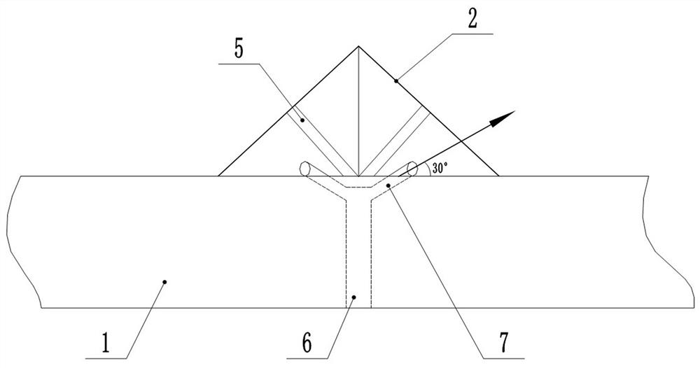
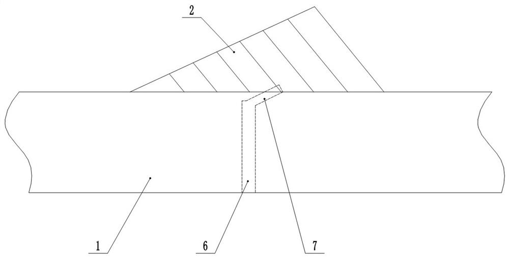
[0021] The scraper 2 is in the shape of a plowshare, and the cutterhead 1 body is provided with a nozzle 6 for introducing high-pressure water. The end of the nozzle 6 is provided with a pair of nozzles 7 positioned below the scraper 2. 7 The penetrating power of the sprayed water to the face of the face, the angle between the spray direction of the spray head 7 and the surface of the cutterhead 1 body is 30°.

[0022] This structural design can effectively prevent the dregs from clogging the nozzle 7 ...


PUM


Abstract

The invention provides a tunnel boring machine cutterhead for assisting rock breaking through a high-pressure water jet. The cutterhead comprises a cutterhead body, a first hob assembly, a second hobassembly and a scraper, wherein the first hob assembly, the second hob assembly and the scraper are arranged on the cutterhead body. Each of the first hob assembly and the second hob assembly comprises a rotating shaft and a plurality of hobs arranged on the rotating shaft. The scraper is plowshare-shaped, a spray pipe used for introducing high-pressure water is arranged on the cutter head body and located below the scraper, a pair of spray heads is arranged at the end of the spray pipe, and the included angle between the spray direction of the spray heads and the surface of the cutter head body is 30 degrees. The rotating areas of the first hob assembly and the second hob assembly are intersected. The first hob assembly is provided with hobs which move along the spraying track of each spray head on the tunnel face. According to the cutterhead, the scraper, the hob and the high-pressure water jet are mutually combined to efficiently crush the tunnel face in the tunneling process, so that the service life of the scraper and the hob can be prolonged, and the tunneling efficiency of the tunnel is greatly improved.

Description

technical field [0001] The invention relates to the technical field of roadheading machine equipment, in particular to a tunnel boring machine cutter head with high-pressure water jet assisting rock breaking. Background technique [0002] Tunnel boring machine is a continuous operation with mechanical crushing of rocks, excavation and support. It is a factory-like assembly line tunnel construction equipment integrating mechanical, electrical, hydraulic, optical, and gas systems. The equipment consists of a front shield, a support shield, and a telescopic shield. , stop shield, knife plate, and rear supporting components. According to the cutting process of the roadheader on the working face, it is divided into full-section roadheader and partial-section roadheader. According to different principles of rock crushing, it can be divided into rolling type (disc hob) roadheader and milling type roadheader. Most of the Chinese products are roller-type full-face roadheaders, whic...

Claims


Application Information

Patent Timeline
Patent Type & Authority Applications(China)
IPC IPC(8): E21D9/087E21D9/10
CPCE21D9/087E21D9/1066
Inventor 孙振中王凯赵海雷陈桥张继超郭璐陈瑞祥杨振兴孙飞祥吕乾乾许华国王发民王利明翟乾智
Owner STATE KEY LAB OF SHIELD & TUNNELING TECH
Learn More