
Power battery and cooling device and method thereof

A power battery and cooling device technology, applied in secondary batteries, battery temperature control, circuits, etc., can solve the problems of potential safety hazards, slow heat dissipation, poor effect, etc., to avoid combustion and explosion, reduce damage, avoid burning effect

Active Publication Date: 2020-12-29
HENAN UNIV OF SCI & TECH
View PDF12 Cites 5 Cited by
  • Summary
  • Abstract
  • Description
  • Claims
  • Application Information

AI Technical Summary

Problems solved by technology

[0005] At present, power batteries generally rely on natural cooling or liquid cooling to cool down. The effect of natural cooling is poor, which is not conducive to the rapid heat dissipation of power batteries; liquid cooling generally uses water cooling, but due to the large specific heat capacity of water, water absorbs The rate of dissipating heat after heat is relatively slow. In the continuous cycle water cooling system, the cooling water that absorbs the heat of the battery cannot be cooled quickly. In the next cooling cycle, the difference between the water temperature and the body temperature of the battery is not large, which is not conducive to the rapid heat dissipation of the power battery. As a result, its heat dissipation rate cannot keep up with the heating rate of the power battery, so that with the accumulation of use time, there will be certain safety hazards

Method used


Image

  • Power battery and cooling device and method thereof
  • Power battery and cooling device and method thereof
  • Power battery and cooling device and method thereof

Examples


Embodiment Construction

[0023] The present invention will be described in further detail below in conjunction with the accompanying drawings and embodiments, but not as a basis for any limitation of the invention.

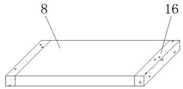
[0024] Referring to the drawings, there is a cooling device for a power battery, the power battery includes a protective casing 1 , and the cooling device is arranged in the protective casing 1 to cool and dissipate the battery body 2 also arranged in the protective casing 1 . The cooling device includes a heat pipe 3 , a cooling chamber 5 , a refrigeration device and a temporary storage chamber 12 . The heat dissipation pipe 3 has a spiral structure and is sleeved on the outer wall of the battery body 2 . The cooling chamber 5 and the temporary storage chamber 12 are both arranged on the same side of the battery body 2 , and the cooling chamber 5 is located above the temporary storage chamber 12 , and the inner surface of the cooling chamber 5 is fixed with a first The liquid pump 4, t...


PUM


Abstract

The invention relates to a power battery and a cooling device and a cooling method thereof. The cooling device of the power battery comprises a heat dissipation pipe, a cooling chamber, a refrigeration device and a temporary storage chamber which are arranged in a power battery protection shell, wherein the refrigeration device is arranged at one side of the cooling chamber and cools a cooling liquid to enter the heat dissipation pipe in the cooling chamber, the temporary storage chamber is used for receiving the cooling liquid absorbing heat in the heat dissipation pipe, and liquid pumps controlled by a single-chip microcomputer and a relay are arranged between the cooling chamber and the input end of the heat dissipation pipe, between the temporary storage chamber and the output end of the heat dissipation pipe and between the cooling chamber and the temporary storage chamber respectively so as to achieve circulation of the cooling liquid. According to the cooling method, in circulation of a cooling liquid, the cooled medium to enter the heat dissipation pipe and the cooled medium which comes out of the heat dissipation pipe and absorbs heat are thoroughly separated, and the cooling effect is good. According to the invention, the heat dissipation rate of the power battery can be increased, so that the safety of the power battery is improved.

Description

technical field [0001] The invention belongs to the technical field of batteries, and in particular relates to a power battery, a cooling device and a cooling method thereof. Background technique [0002] A battery refers to a part of the space of a cup, tank or other container or composite container that contains an electrolyte solution and metal electrodes to generate electric current, a device that can convert chemical energy into electrical energy. With the rapid development of modern technology, the types of batteries have become more and more. More and more, the power battery is one of them. The power battery is the power source that provides the power source for the tool, and mostly refers to the battery that provides power for electric vehicles, electric trains, electric bicycles, and golf carts. Power batteries include power lithium batteries, lead-acid power batteries, nickel-hydrogen power batteries, etc. [0003] In the process of using the existing power batte...

Claims


Application Information

Patent Timeline
Patent Type & Authority Applications(China)
IPC IPC(8): H01M10/613H01M10/625H01M10/6556H01M10/6567H01M10/657H01M10/63
CPCH01M10/613H01M10/625H01M10/6556H01M10/6567H01M10/657H01M10/63Y02E60/10
Inventor 白晓天郭志军陈镜宇张盼港郭福贵司胜洁尹亚昆郑帅杰省东旭
Owner HENAN UNIV OF SCI & TECH
Learn More