
A method for monitoring switching force of a switch machine

A switch machine and force sensor technology, applied in force/torque/power measuring instruments, measuring force, measuring devices, etc., can solve the problems of poor timeliness and cumbersome process of measurement methods, and achieve good timeliness, accurate acquisition, and data Accurate and reliable results

Active Publication Date: 2021-12-03
DALIAN UNIV OF TECH +1
View PDF0 Cites 0 Cited by
  • Summary
  • Abstract
  • Description
  • Claims
  • Application Information

AI Technical Summary

Problems solved by technology

[0004] In order to solve the problems of poor timeliness and cumbersome process of existing measurement methods, the present invention proposes a method for monitoring switching force of switch machines

Method used


Image

  • A method for monitoring switching force of a switch machine
  • A method for monitoring switching force of a switch machine
  • A method for monitoring switching force of a switch machine

Examples


Embodiment Construction

[0024] The specific implementation manners of the present invention will be further described below in conjunction with the accompanying drawings and technical solutions.

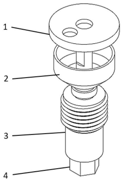
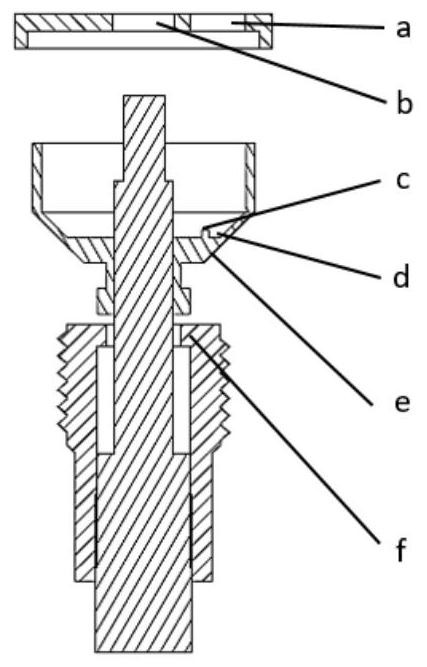
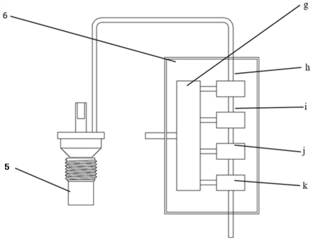
[0025] The measuring device used among the present invention comprises conversion force sensor 5 and conversion force collector 6, and concrete composition and connection relation are as Fig. 1 (a) and Fig. 1 (b) and figure 2 shown.

[0026] In this embodiment, the material of the switch machine action rod is steel, and the conversion force sensor 5 is installed in the through hole located at the neutral axis. The shape and size of the tapered hole match the conversion force sensor 5, and its upper part is a straight hole. The diameter is 17mm, the depth is 20mm, and the middle section is a conical structure, which is matched with the outer conical surface e of the conical cylinder structure at the lower part of the conical force-sensitive structure 2. The lower half is a straight hole and the surface is pr...


PUM

PropertyMeasurementUnit
elastic modulusaaaaaaaaaa
diameteraaaaaaaaaa
depthaaaaaaaaaa

Abstract

The invention belongs to the field of force measurement and relates to a method for monitoring switching force of a switch machine. In the present invention, the conversion force sensor is installed on the action rod inside the switch machine, and the conversion force sensor is installed in the through hole opened on the neutral axis of the action rod. The change of force and strain of the action rod causes the deformation of the conversion force sensor, and then passes The conversion force collector obtains and outputs the strain signal, realizing the real-time monitoring of the conversion force of the switch machine. Compared with the current method for measuring the force of the switch machine, the present invention can reflect the working state of the switch machine when it is in service, and the obtained data has better timeliness.

Description

technical field [0001] The invention belongs to the field of force measurement, and in particular relates to a method for monitoring switching force of a switch machine. Background technique [0002] The electric switch machine is an electrical device used to change the direction of the turnout on the railway, and its stable operation is directly related to the safety of railway transportation. After the switch machine motor passes through the reducer and the worm gear, it provides power to drive the action rod to move the switch. The driving force is called the switch conversion force. When the switching force of the switch machine is too large, the switch rail and the basic rail will squeeze each other. Under long-term action, the basic rail will be deformed, which will affect the driving safety; when the switching force of the switch machine is too small, the switch rail will not move properly. , the train will have the risk of derailment, endangering traffic safety. Th...

Claims


Application Information

Patent Timeline
Patent Type & Authority Patents(China)
IPC IPC(8): G01L5/00G01L1/22
CPCG01L1/22G01L5/0028
Inventor 王大志张天赋马韬皮立新翟文革谢明军卢智丁召荣陈玉亮戴恒震梁军生任同群赵剑崔扬马振人齐雪梅张媛
Owner DALIAN UNIV OF TECH
Learn More