Shield working well connector drainage structure and construction method thereof

A drainage structure and working well technology, applied in drainage, wellbore lining, shaft equipment, etc., can solve problems such as general service life and reliability of components, difficulty in increasing maintenance, difficulty in realizing self-waterproofing of concrete, etc., and achieve easy control of construction quality, Reduce post-maintenance work, and the overall waterproof effect is good

Pending Publication Date: 2020-12-29
GUANGZHOU METRO DESIGN & RES INST +1
View PDF0 Cites 0 Cited by
  • Summary
  • Abstract
  • Description
  • Claims
  • Application Information

AI Technical Summary

Problems solved by technology

[0003] The size of the shield working well interface is larger than the shield segment structure size, and the gap between the shield working well interface and the shield segment is generally sealed by post-casting ring beams. There are cold joints after the shrinkage of the concrete, which makes it difficult to realize the self-waterproofing of the concrete, and it is easy for the groundwater outside the working well to infiltrate into the working well from the cold joints of the concrete structure and laterally, which will adversely affect the operation and maintenance of the structure
[0004] In order to solve the above technical problems, in the prior art, stainless steel sinks are generally used for the drainage of structural joints, but the maintenance period is short, and the service life and reliability of components are average; and the seepage point of the shield working well interface is generally located in the working well Directly above, the maintenance work needs to occupy a large space, and the available maintenance time is less, which further increases the difficulty of maintenance. It is particularly important to study reliable drainage methods to avoid adverse effects on the use of shield tunnels.

Method used


Image

  • Shield working well connector drainage structure and construction method thereof
  • Shield working well connector drainage structure and construction method thereof
  • Shield working well connector drainage structure and construction method thereof

Examples


Embodiment Construction

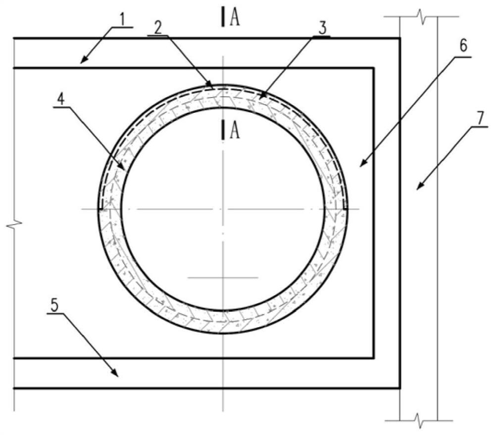
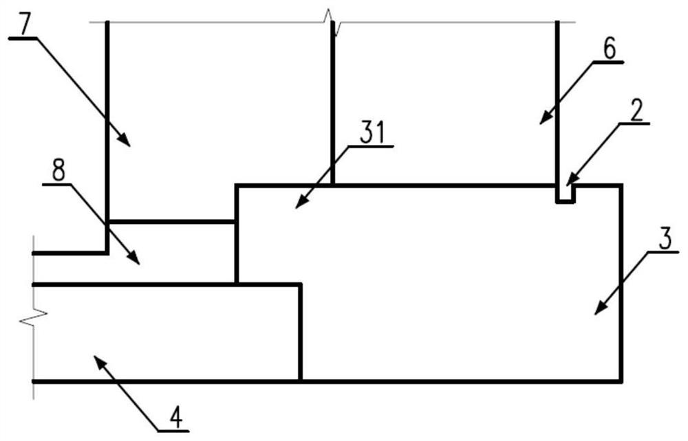
[0027] The specific implementation manners of the present invention will be further described in detail below in conjunction with the accompanying drawings and embodiments. The following examples are used to illustrate the present invention, but are not intended to limit the scope of the present invention.

[0028] In the description of the present invention, it should be understood that the orientation or positional relationship indicated by the terms "upper", "lower", "left", "right", "top", "bottom" etc. Orientation or positional relationship is only for the convenience of describing the present invention and simplifying the description, and does not indicate or imply that the referred device or element must have a specific orientation, be constructed and operated in a specific orientation, and thus should not be construed as a limitation of the present invention. It should be understood that the terms "first", "second", etc. are used in the present invention to describe va...


PUM


Abstract

The invention discloses a shield working well connector drainage structure and a construction method thereof. The shield working well connector drainage structure comprises a shield segment, a shieldworking well and a post-cast ring beam used for connecting the shield segment with the shield working well, wherein a shield working well end wall is arranged at the end of the shield working well andprovided with a connector; the left side of the post-cast ring beam is connected with the shield segment; the outer side face of the post-cast ring beam is covered with the section of the connector;the upper half portion of the post-cast ring beam is provided with an extending section extending to the right side of the shield working well end wall; a drainage ditch is formed in the side face ofan upper semicircular ring of the extending section; and the left side wall of the drainage ditch is flush with the inner side face of the shield working well end wall. According to the shield workingwell connector drainage structure and the construction method thereof, water seepage of a lateral joint of the post-cast ring beam and the working well end wall can be drained in an organized mode, the water guiding and draining effect is good, the total input cost is low, and the situation that normal operation of a shield tunnel is affected by water seepage of the shield connector is avoided.

Description

technical field [0001] The invention relates to the technical field of traffic engineering construction, in particular to a shield working well interface drainage structure and a construction method thereof. Background technique [0002] With the acceleration of urbanization, the urban population, regional planning and urban ecological environment are facing enormous pressure. The development and utilization of urban underground space is the solution to the above pressure. In the process of underground engineering construction, the shield tunnel is to meet the needs of the shield machine. Generally, it is necessary to set up a shield working shaft to realize the origination or reception of the shield. Usually, a shield is reserved on the end wall of the shield working shaft structure. The hole through which the shield machine passes is usually called the shield working well interface. The outsourcing waterproof of the working well is disconnected at the shield working well i...

Claims


Application Information

Patent Timeline
Patent Type & Authority Applications(China)
IPC IPC(8): E21D11/08E21D11/10E21D11/38E21F16/02
CPCE21D11/08E21D11/10E21D11/38E21F16/02
Inventor 李志南潘珂王位赢罗文静黄钟晖王炳华农兴中雷振宇马少坤袁江区杨荫黄全强陈骏胡浩曾军
Owner GUANGZHOU METRO DESIGN & RES INST
Why Eureka
Try Eureka