
Metallurgical slag pot grating convenient to disassemble and assemble

A slag tank and grid technology, applied in the field of metallurgical slag tank grid, can solve the problems of inconvenient production and use, inconvenient assembly, etc., and achieve the effects of stable placement, stable assembly structure and easy use.

Pending Publication Date: 2020-12-29
MAANSHAN CITY MODEL PRODUCTIVITY PROMOTION CENT CO LTD
View PDF10 Cites 1 Cited by
  • Summary
  • Abstract
  • Description
  • Claims
  • Application Information

AI Technical Summary

Problems solved by technology

[0005] Aiming at the deficiencies of the prior art, the present invention provides a metallurgical slag tank grid that is easy to disassemble and assemble. Grille is used for classification in the tank, and the interior of the slag tank is divided into several small spaces for the subsequent treatment of steel slag, but the assembly of the horizontal and vertical grid plates that make up the grid is inconvenient, and it is not convenient for actual production and use. question

Method used


Image

  • Metallurgical slag pot grating convenient to disassemble and assemble
  • Metallurgical slag pot grating convenient to disassemble and assemble
  • Metallurgical slag pot grating convenient to disassemble and assemble

Examples


Embodiment Construction

[0027] The technical solutions in the embodiments of the present invention will be clearly and completely described below. Obviously, the described embodiments are only some of the embodiments of the present invention, but not all of them. Based on the embodiments of the present invention, all other embodiments obtained by persons of ordinary skill in the art without making creative efforts belong to the protection scope of the present invention.

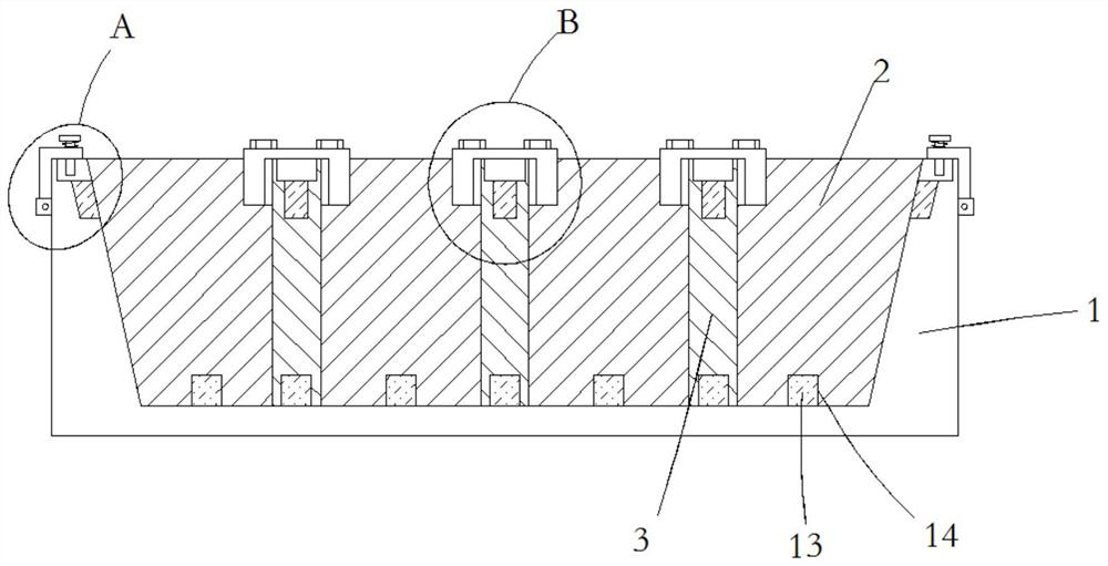
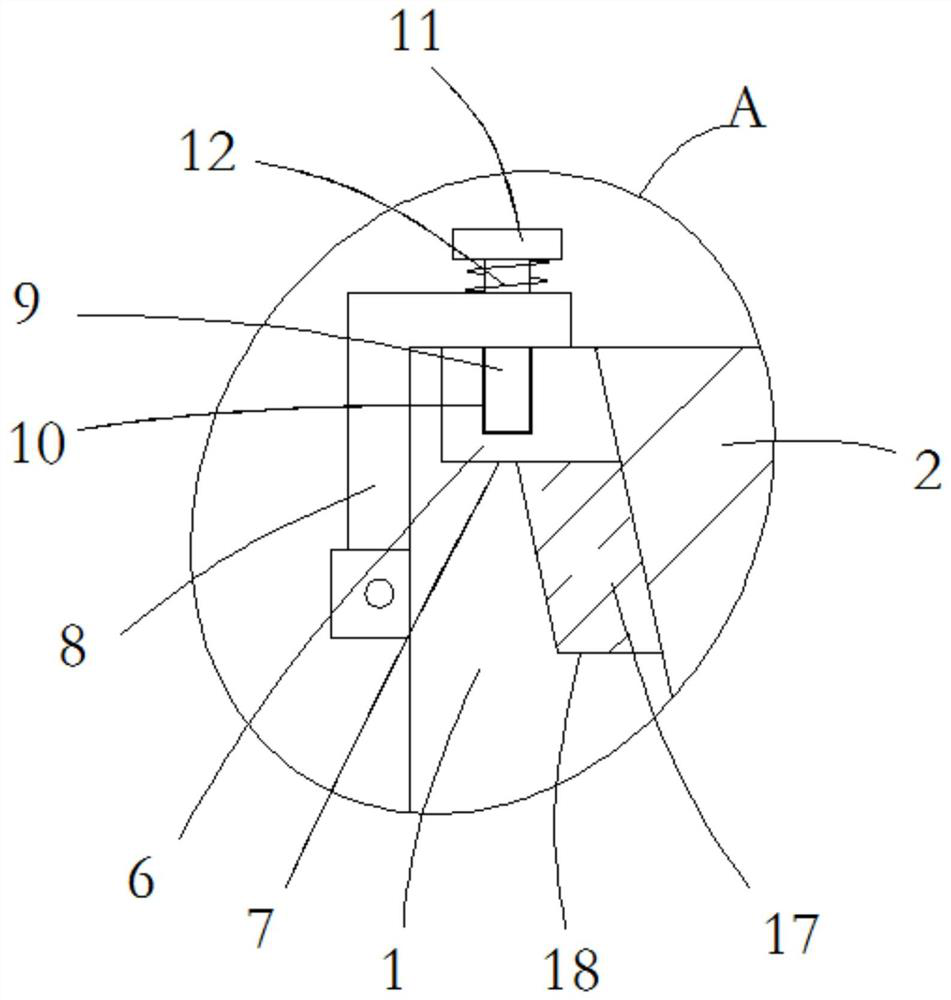
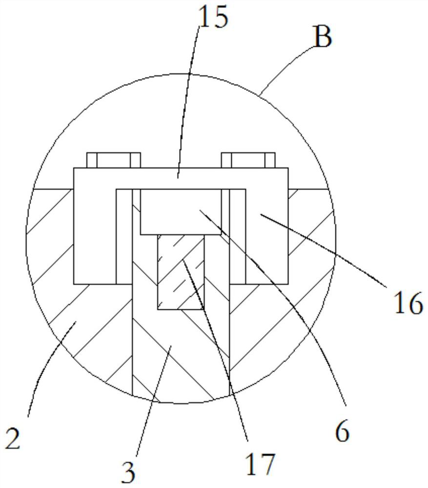
[0028] see Figure 1-5 , a metallurgical slag tank grating that is easy to disassemble, including a slag tank 1 and a plurality of transverse grid plates 2 and longitudinal grid plates 3 installed in the slag tank 1, a plurality of transverse grid plates 2 and longitudinal grid plates The grid plates 3 are clamped together, the upper end of the horizontal grid plate 2 is evenly provided with a plurality of upper clamping grooves 4, and the lower end of the longitudinal grid plate 3 is provided with a plurality of lower clamping groo...


PUM


Abstract

The invention relates to the technical field of slag pot gratings, and discloses a metallurgical slag pot grating convenient to disassemble and assemble. The metallurgical slag pot grating comprises aslag pot, a plurality of transverse grating plates and a plurality of longitudinal grating plates, the transverse grating plates and the longitudinal grating plates are arranged in the slag pot, themultiple transverse grating plates and the multiple longitudinal grating plates are clamped together, a plurality of upper clamping grooves are uniformly formed in the upper ends of the transverse grating plates, a plurality of lower clamping grooves are formed in the lower ends of the longitudinal grating plates, the transverse grating plates and the longitudinal grating plates are mutually clamped together through matching of the upper clamping grooves and the lower clamping grooves, clamping blocks are fixedly connected to the two ends of the transverse grating plates and the two ends of the longitudinal grating plates, and a plurality of clamping notches correspondingly clamped with the clamping blocks are formed in the upper end of the slag tank; and a plurality of L-shaped crimping plates are symmetrically and rotatably connected to the outer wall of the upper end of the slag tank, and horizontal parts of the L-shaped crimping plates are crimped at the upper ends of the clampingblocks. The metallurgical slag pot grating convenient to disassemble and assemble has the advantages that the grating can be rapidly assembled, so that the assembly structure of the grating is stable,and the use is convenient.

Description

technical field [0001] The invention relates to the technical field of slag tank grids, in particular to a metallurgical slag tank grid which is easy to assemble and disassemble. Background technique [0002] Steelmaking slag steel is a mixture of steel slag and a small part of residual molten steel produced during steelmaking casting billet or continuous casting production. These mixtures will form large steel ingots after cooling in the slag tank. At present, iron and steel enterprises generally use methods such as oxygen cutting and vertical slamming to cut large steel ingots into small pieces for recycling steelmaking. This treatment method has the disadvantages of high cutting cost, large energy consumption, and environmental pollution. In addition, the amount of iron oxide loss and waste caused by oxygen cutting is staggering every year, causing losses to enterprises. [0003] At present, grids are used for classification in slag tanks, and the interior of the slag t...

Claims


Application Information

Patent Timeline
IPC IPC(8): C21B3/10
CPCC21B3/10
Inventor 张良贵
Owner MAANSHAN CITY MODEL PRODUCTIVITY PROMOTION CENT CO LTD
Learn More