Watch lens grinding equipment

A lens and equipment technology, applied in the field of watch lens grinding equipment, to achieve the effect of smooth surface, uniform grinding, and avoiding limited range of motion

Pending Publication Date: 2020-12-29
JIANGSU SAIBO YUHUA TECH CO LTD
View PDF0 Cites 0 Cited by
  • Summary
  • Abstract
  • Description
  • Claims
  • Application Information

AI Technical Summary

Problems solved by technology

[0005] For this reason, the present invention provides a watch lens grinding equipment, by installing the lens material of the watch on the clamping device, by setting the moving device, the lifting device, the horizontal rotation device, the angle adjustment device and the vertical rotation device to cooperate, to solve the automation The problem of convenient and flexible operation of the grinding device for grinding the watch mirror

Method used


Image

  • Watch lens grinding equipment
  • Watch lens grinding equipment
  • Watch lens grinding equipment

Examples


Embodiment 1

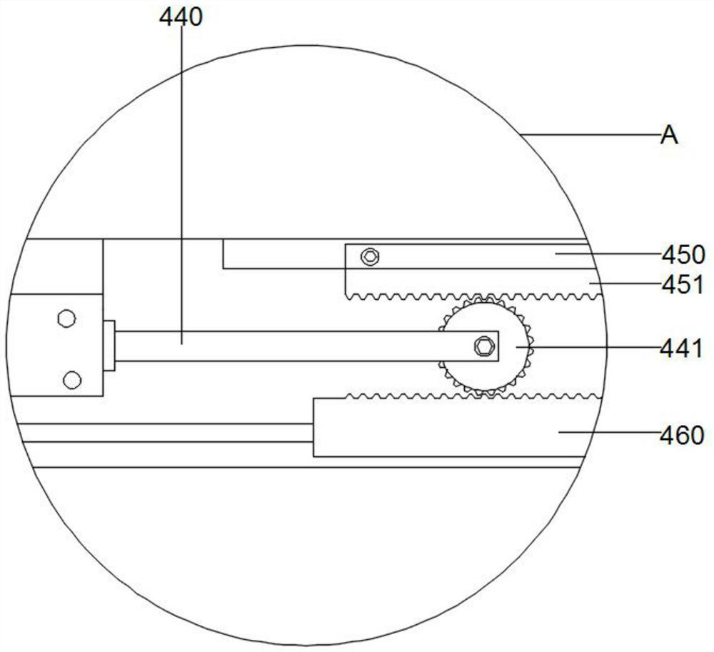
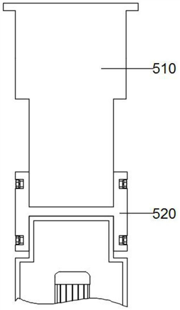
[0026] Refer to attached Figure 1-5 , a kind of watch lens polishing equipment provided by the present invention, comprises base 100, workbench 200, clamping device 300, moving device 400, lifting device 500, horizontal rotation device 600, angle adjustment device 700, vertical rotation device 800 and grinding device 900, specifically, the base 100 includes a horizontal plate 110, the top of the horizontal plate 110 is fixedly installed with a vertical pole 120, the top of the base 100 is provided with a workbench 200, the top of the workbench 200 is fixed with a clamping device 300, and the top of the vertical pole 120 is fixedly installed with a moving device 400, the bottom of the moving device 400 is fixedly connected to the lifting device 500, the top of the lifting device 500 is fixedly connected to the horizontal rotation device 600, the bottom of the horizontal rotation device 600 is flexibly connected to the angle adjustment device 700, the bottom of the angle adjustm...

Embodiment 2

[0037] Refer to attached Figure 6 , a kind of watch lens polishing equipment provided by the present invention, comprises base 100, workbench 200, clamping device 300, moving device 400, lifting device 500, horizontal rotation device 600, angle adjustment device 700, vertical rotation device 800 and grinding device 900;

[0038] Further, the clamping device 300 also includes a servo motor 2 350, the servo motor 2 350 is fixedly installed on the inner and outer wall of the vertical rod 120, two sets of servo motor 350 are symmetrically arranged, and the output end of the servo motor 2 350 is fixedly connected to the rotating block 351, The inner wall of the rotating block 351 is plugged with the cylinder three 360, the output end of the cylinder three 360 ​​is fixedly installed with a protective pad 361, the servo motor two 350 is set as C-PLX310, and the servo motor two 350 has the function of driving the grinding blade 930 to perform rotary grinding, and the rotating block 3...


PUM


Abstract

The invention discloses watch lens grinding equipment. According to the technical scheme, the watch lens grinding equipment comprises a base, a workbench, a clamping device, a moving device, a liftingdevice, a horizontal rotating device, an angle adjusting device, a longitudinal rotating device and a grinding device, the base comprises a transverse plate, a vertical rod is fixedly installed at the top of the transverse plate, the workbench is arranged at the top of the base, the clamping device is fixedly installed at the top of the workbench, the moving device is fixedly installed at the topof the vertical rod, the bottom of the moving device is fixedly connected with the lifting device, the top of the lifting device is fixedly connected with the horizontal rotating device, and the bottom of the horizontal rotating device is movably connected with the angle adjusting device. the bottom of the angle adjusting device is movably connected with the longitudinal rotating device, and thebottom of the longitudinal rotating device is movably connected with the grinding device. The watch lens grinding device has the beneficial effects that the lifting device, the horizontal rotating device and the angle adjusting device are arranged to be used in cooperation, and therefore a lens can be polished in a full-method mode.

Description

technical field [0001] The invention relates to the technical field of watch lens grinding, in particular to a watch lens grinding device. Background technique [0002] A watch, or a watch, refers to an instrument worn on the wrist for timing and displaying time. Usually, the lens on the display surface of the watch needs to be produced during the production of the watch. The lens has the functions of protection and waterproof. It may also cause wear or damage to the surface and require regrinding to install new lenses. [0003] The existing technology has the following disadvantages: the existing ones usually need to be manually polished by the staff. This method generally has low work efficiency, and there may be a little danger. The novice’s misuse may cause damage to his hands. damage. [0004] Therefore, it is necessary to invent a kind of watch lens polishing equipment. Contents of the invention [0005] To this end, the present invention provides a watch lens gri...

Claims


Application Information

Patent Timeline
Patent Type & Authority Applications(China)
IPC IPC(8): B24B19/22B24B41/06B24B41/02B24B47/14B24B47/22B24B47/12B24B41/04
CPCB24B19/22B24B41/02B24B41/04B24B41/06B24B47/12B24B47/14B24B47/22
Inventor 肖建军
Owner JIANGSU SAIBO YUHUA TECH CO LTD
Why Eureka
Try Eureka