High-voltage test equipment configured with relay protection and safety monitoring system thereof

A technology of safety monitoring system and high-voltage test, which is applied to the components of electrical measuring instruments, measuring electronics, measuring devices, etc., can solve the problems of single detection platform, single structure and function, manual operation of fire extinguishing equipment, etc. Position, improve the effect of test efficiency

Pending Publication Date: 2021-12-10
华能(浙江)能源开发有限公司长兴分公司
View PDF0 Cites 0 Cited by
  • Summary
  • Abstract
  • Description
  • Claims
  • Application Information

AI Technical Summary

Problems solved by technology

[0003] In the existing technology, some test equipments have relatively simple structure and functionality, and the detection platform is relatively single. For example, the high-voltage test equipment that can only detect transformers cannot detect switches, and the actual mobility of such equipment itself is relatively poor. While it is not convenient to move, it does not have the function of fire extinguishing protection. Therefore, when the equipment is moved, it also needs to carry fire extinguishing equipment. While it is inconvenient to carry, this type of fire extinguishing equipment needs manual operation. The existing high-voltage test equipment cannot extinguish the fire by itself, so it cannot stop the spread of the fire
[0004] Moreover, the existing high-voltage tests seldom consider the influence on the tested components under environmental changes. If the tested components are in normal use, especially in rainy weather, factors such as air humidity will affect the tested components. The performance of detection components is affected by the

Method used


Image

  • High-voltage test equipment configured with relay protection and safety monitoring system thereof
  • High-voltage test equipment configured with relay protection and safety monitoring system thereof
  • High-voltage test equipment configured with relay protection and safety monitoring system thereof

Examples


Embodiment Construction

[0028] The following will clearly and completely describe the technical solutions in the embodiments of the present invention with reference to the accompanying drawings in the embodiments of the present invention. Obviously, the described embodiments are only some, not all, embodiments of the present invention. Based on the embodiments of the present invention, all other embodiments obtained by persons of ordinary skill in the art without making creative efforts belong to the protection scope of the present invention.

[0029] In the description of the present invention, it should be noted that the terms "upper", "lower", "inner", "outer", "front end", "rear end", "both ends", "one end", "another end" The orientation or positional relationship indicated by etc. is based on the orientation or positional relationship shown in the drawings, and is only for the convenience of describing the present invention and simplifying the description, rather than indicating or implying that ...


PUM


Abstract

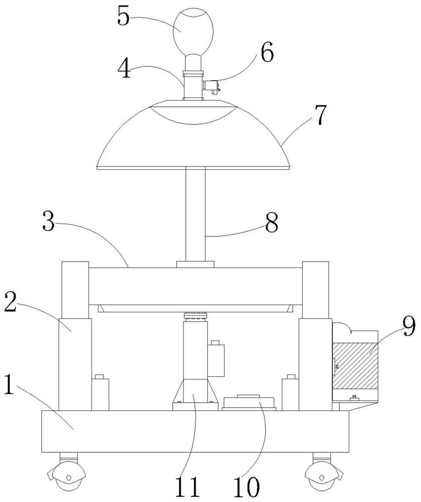
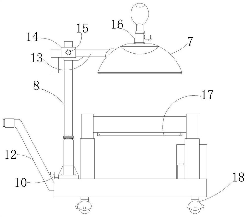
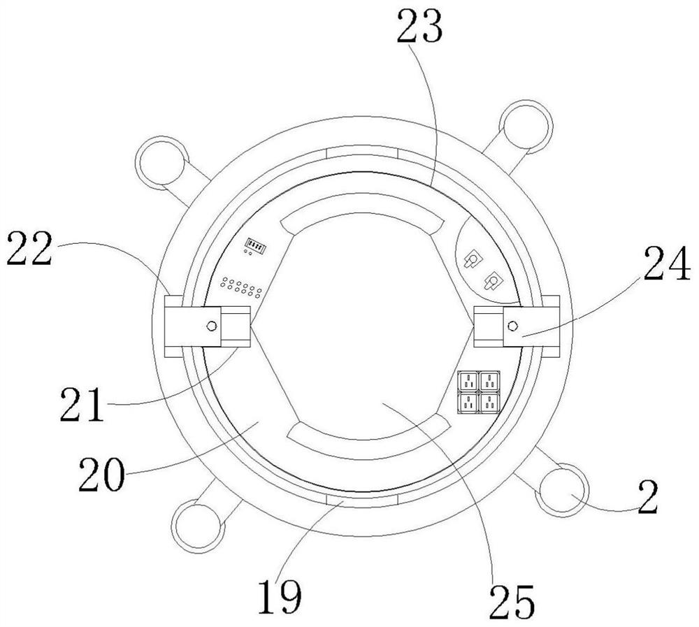
The invention discloses high-voltage test equipment configured with relay protection and a safety monitoring system thereof. The high-voltage test equipment comprises a bottom plate and universal wheels installed at the bottom end of the bottom plate. The top ends of second telescopic supporting rods are jointly provided with a detection disc, a main detection plate is installed in a conduction groove of the detection disc through a rotating shaft piece, and a sub detection plate is installed at the bottom end of the main detection plate. Limiting mechanisms are installed on the edges of the surfaces of the main detection plate and the sub detection plate correspondingly. A functional power source mechanism is installed in a functional box. A rotating adjusting mechanism is installed at the top end of a supporting rod, a safety cover is installed on the rotating adjusting mechanism, a supply mechanism is installed at the top end of the safety cover, and a monitoring safety mechanism is installed in the safety cover. By arranging a series of structures, the high-voltage test equipment can carry out diversified high-voltage tests on the upper layer and the lower layer, has remote control and safety protection functions, is flexible to use, can simulate a rainy day environment to carry out tests, and improves the test functionality.

Description

technical field [0001] The invention relates to the technical field of thermal power equipment safety, in particular to a high-voltage test equipment equipped with relay protection and a safety monitoring system thereof. Background technique [0002] There are many types of existing high-voltage test equipment, generally for high-voltage test operations on transformers, switches, lightning arresters, transformers and other components, which need to be fixed at specific positions, and when testing different components, the test components on it are relatively simple. [0003] In the existing technology, some test equipments have relatively simple structure and functionality, and the detection platform is relatively single. For example, the high-voltage test equipment that can only detect transformers cannot detect switches, and the actual mobility of such equipment itself is relatively poor. While it is not convenient to move, it does not have the function of fire extinguishi...

Claims


Application Information

Patent Timeline
Patent Type & Authority Applications(China)
IPC IPC(8): G01R1/02G01R1/04A62C3/16A62C31/00
CPCG01R1/02G01R1/04G01R1/0408A62C3/16A62C31/005
Inventor 冯伯瑾孙迪沈向忠薄鼎彪黄杰李国强沈永根莫新颜秦永昆吕冠澎吴勇兴
Owner 华能(浙江)能源开发有限公司长兴分公司
Why Eureka
Try Eureka