
Divergent nut conveying device and use method thereof

A conveying device and nut technology, applied in auxiliary devices, auxiliary welding equipment, welding/cutting auxiliary equipment, etc., can solve the problems of increasing labor workload, inconvenient use, time-consuming and labor-intensive, etc.

Pending Publication Date: 2019-05-28
广州市永汇自动化设备有限公司
View PDF1 Cites 0 Cited by
  • Summary
  • Abstract
  • Description
  • Claims
  • Application Information

AI Technical Summary

Problems solved by technology

[0004] 1. When using the conveying pipe for nut input, the position of the conveying pipe cannot be changed, resulting in the need to continuously move the entire device to input nuts when conveying nuts at different positions, which increases the workload of laborers At the same time, it is inconvenient to use, and it is time-consuming and labor-intensive;
[0005] 2. Since the width of the sliding groove is fixed, the sliding range of the nut conveying pipe in the sliding groove cannot be adjusted according to the position of the nut welding machine, and it is easy to cause the nut to fall directly from the conveying pipe when used on an unmatched nut welding machine. Dropped to the floor, causing inconvenience during use

Method used


Image

  • Divergent nut conveying device and use method thereof
  • Divergent nut conveying device and use method thereof
  • Divergent nut conveying device and use method thereof

Examples


Embodiment Construction

[0028] The following will clearly and completely describe the technical solutions in the embodiments of the present invention with reference to the accompanying drawings in the embodiments of the present invention. Obviously, the described embodiments are only some, not all, embodiments of the present invention. Based on the embodiments of the present invention, all other embodiments obtained by persons of ordinary skill in the art without making creative efforts belong to the protection scope of the present invention.

[0029] In the description of the present invention, it should be noted that the terms "upper / lower end", "inner", "outer", "front end", "rear end", "both ends", "one end", "another end" etc. indicate The orientation or positional relationship is based on the orientation or positional relationship shown in the drawings, and is only for the convenience of describing the present invention and simplifying the description, rather than indicating or implying that the...


PUM


Abstract

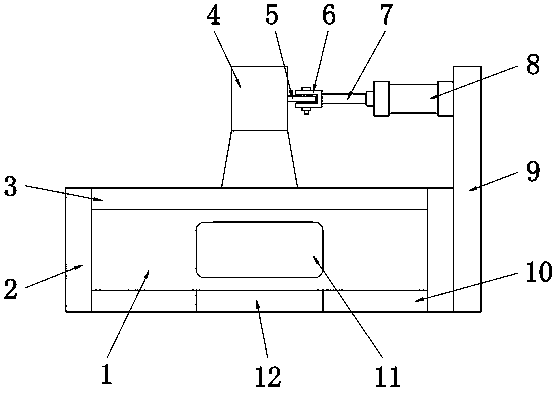
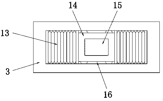
The invention relates to the field of automobile manufacturing, in particular to a divergent nut conveying device and a use method of the divergent nut conveying device. The divergent nut conveying device comprises a base plate. A back baffle is fixed to the upper surface of the base plate. The upper surface of the base plate is fixedly provided with a front baffle. The two sides of the upper surface of the base plate are symmetrically and fixedly provided with side plates. The two side plates are both fixedly connected with the two sides of the front baffle and the back baffle. The outer surface wall of the front baffle is provided with a sliding groove. A limiting groove is formed in the center of the upper surface of the base plate. A moving groove is formed on the back baffle, a connection plate is connected into the moving groove through first sliding grooves and sliding wheels. A conveying pipe communicates with a communication opening of the connection plate. A fixing plate is fixed to one side of one side plate, and an air cylinder is fixed to one side of the fixing plate. A connection block at one end of the air cylinder is fixedly connected with a connection sheet on theconveying pipe. In this way, the air cylinder conveniently drives the connection plate to move left and right in the moving groove, and therefore nut conveyance at different positions can be achieved.

Description

technical field [0001] The invention relates to the field of automobile manufacturing, in particular to a nut fork conveying device and a method for using the same. Background technique [0002] With the development of our country's economic level, people's living standards are also improving. Therefore, most people choose to buy cars as a means of transportation, which leads to the rapid development of the automobile manufacturing industry. The role of nuts in automobile manufacturing is particularly important. , so the nut conveying device is manufactured for conveying nuts in the production of automobiles. [0003] Chinese patent (CN201711269112.7, Repeated Nut Bifurcated Conveying Mechanism and Method of Use), this patent discloses a repetitive nut bifurcated conveying mechanism, including the first cylinder, the second cylinder, the third cylinder, the bottom plate, the connecting plate, the A limit block, a second limit block and a nut, the bottom plate is provided wi...

Claims


Application Information

Patent Timeline
Patent Type & Authority Applications(China)
IPC IPC(8): B23K37/00
Inventor 张文星
Owner 广州市永汇自动化设备有限公司
Learn More