
Screen input system and implementation method thereof

A technology of screen input and implementation method, applied in the input/output process of data processing, instruments, electrical digital data processing, etc., can solve the problems of cumbersome manufacturing and installation, occupying space, screen wear, etc., and achieves low manufacturing cost and structure. simple effect

Inactive Publication Date: 2012-05-02
DG HUST MFG ENG RES INST +2
View PDF9 Cites 18 Cited by
  • Summary
  • Abstract
  • Description
  • Claims
  • Application Information

AI Technical Summary

Problems solved by technology

[0006] 1. Touch screen input adopts special equipment, and the cost of upgrading the existing screen is too high. This requires replacing the currently widely used LCD and CRT monitors with touch screen monitors, and the projection screens widely used in teaching, exhibitions, and entertainment. Need to replace with electronic whiteboard
[0007] 2. Electronic whiteboards and laser projection systems are not only expensive, but also take up space, require independent installation and wiring, and the positioning and calibration of the screen is cumbersome
At present, the infrared photoelectric whiteboard adopts the grid format infrared emitting tube and receiving device, which is cumbersome to manufacture and install, and cannot be upgraded on the existing ordinary screen.
[0008] 3. The current gesture input is a contact gesture input, that is, it must be touched or very close to the screen, so there are problems such as screen wear and hygiene, and it is inconvenient to realize contact gesture input on a large projection screen that exceeds the range of human activities

Method used


Image

  • Screen input system and implementation method thereof
  • Screen input system and implementation method thereof
  • Screen input system and implementation method thereof

Examples


Embodiment Construction

[0040] In order to further understand the features, technical means, and specific objectives and functions achieved by the present invention, the present invention will be further described in detail below in conjunction with the accompanying drawings and specific embodiments.

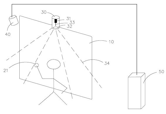
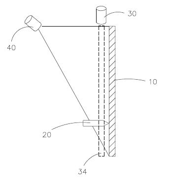
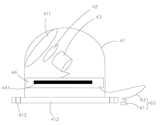
[0041] see Figure 1 to Figure 6, A screen input system of the present invention includes an operation screen 10 , a touch screen device 20 , a laser light curtain transmitter 30 , a receiving device 40 and a computer host 50 . The operation screen 10 can be set as devices of different sizes or materials such as CRT display screens, projection cloths, wall curtains, and LED arrays. The top and bottom of the operation screen 10 are provided with grooves, and the touch screen device 20 is an operator's A finger or pen-type device, the laser light curtain emitter 30 is installed in the top groove of the operation screen 10, and is clamped and fixed by a pre-designed clamping and fixing device. The laser ...


PUM


Abstract

The invention discloses a screen input system and an implementation method of the screen input system and belongs to the technical field of computer input equipment. The screen input system comprises an operating screen, a touch screen device, a laser light screen emitter, a receiving device and a host computer, wherein the receiving device and the laser light screen emitter are installed at one side of the operating screen, the receiving device comprises an infrared filter, a camera module and a signal processing module, a connector communicated with the host computer is arranged at the output end of the signal processing module, the laser light screen emitter is installed on the top of the operating screen, and a light screen is formed on the surface of the operating screen, the touch screen device is contacted with the operating screen, and a reflection light spot is formed at the contact position, the camera module obtains a light reflected from the reflection light spot, and the signal processing module is used for processing the light images obtained by the camera module. The invention has the advantages of low manufacture cost, simple structure, convenience and practicability.

Description

technical field [0001] The present invention relates to the technical field of computer input equipment, in particular to a screen input system and its implementation method. Background technique [0002] With the development of digital technology, the input technology in human-computer interaction is evolving from traditional mouse and keyboard input methods to various input methods. With the popularity of smart phones and tablet computers, a more humane direct screen gesture input method has been widely used, and the latest Windows7 has officially supported the gesture input method, which enables input to be performed directly on the screen used to output images, that is, Direct input on the screen without an external keyboard and mouse. [0003] Patent application CN200810035544.6 discloses a method for laser pointer indication and light spot trajectory recognition, which uses brightness information to extract the position of the light spot indicated by the pointing tool...

Claims


Application Information

Patent Timeline
Patent Type & Authority Applications(China)
IPC IPC(8): G06F3/042
Inventor 王石陆兴友朱河清杨永光施松新李浩治严星汉
Owner DG HUST MFG ENG RES INST
Learn More