
Bearing end face warping preventing non-magnetic grinding device and method

An anti-warping and end-face technology, applied in the field of bearing processing, can solve the problems of sudden increase in normal grinding force, affecting processing accuracy, elastic deformation of the end face, etc., to eliminate elastic warping, improve grinding accuracy, and delay elastic recovery. Effect

Active Publication Date: 2020-12-29
GUANGZHOU UNIVERSITY
View PDF9 Cites 0 Cited by
  • Summary
  • Abstract
  • Description
  • Claims
  • Application Information

AI Technical Summary

Problems solved by technology

[0004] Due to the presence of weak magnetic force, radial clamping force and normal grinding force on the bearing, small elastic deformation in the direction of the end face will still occur for large or soft thin-walled bearings with low stiffness. At the same time, the warping protrusion of the bearing will cause grinding The grinding force in the normal direction increases suddenly during cutting, and the increase in force in this direction will further lead to elastic deformation of the end face, which will affect the final machining accuracy

Method used


Image

  • Bearing end face warping preventing non-magnetic grinding device and method
  • Bearing end face warping preventing non-magnetic grinding device and method
  • Bearing end face warping preventing non-magnetic grinding device and method

Examples


Embodiment 1

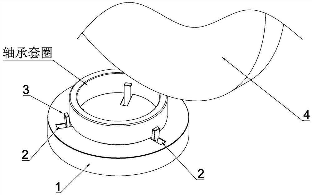
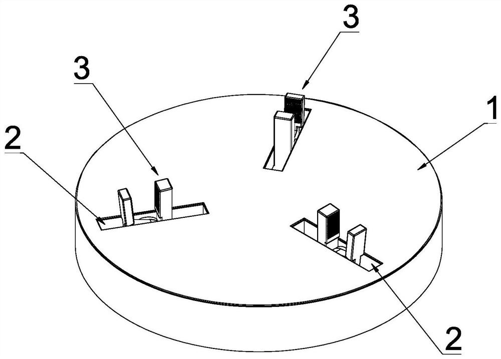
[0043] see Figure 1-Figure 2 , this embodiment discloses a non-magnetic grinding device for preventing warpage of bearing end faces, which includes a workbench 1 arranged on the turntable of the grinder, and the workbench 1 is provided with three slide grooves 2, and the three slide grooves 2 Evenly distributed around the central circumference of the workbench 1, the sliding grooves 2 extend along the radial direction, and each sliding groove 2 is provided with an elastic damping clamping mechanism for clamping the bearing ring and slidingly matching with the sliding groove 2 3. By setting three sliding grooves 2, each sliding groove 2 is evenly distributed in the circumferential direction, and the angle between two adjacent sliding grooves 2 is 120°. Correspondingly, the three elastic damping clamping mechanisms 3 clamp the bearing at the same time When processing the bearing ring, the degree of freedom of the three elastic damping clamping mechanisms 3 on the chute is 0, t...

Embodiment 2

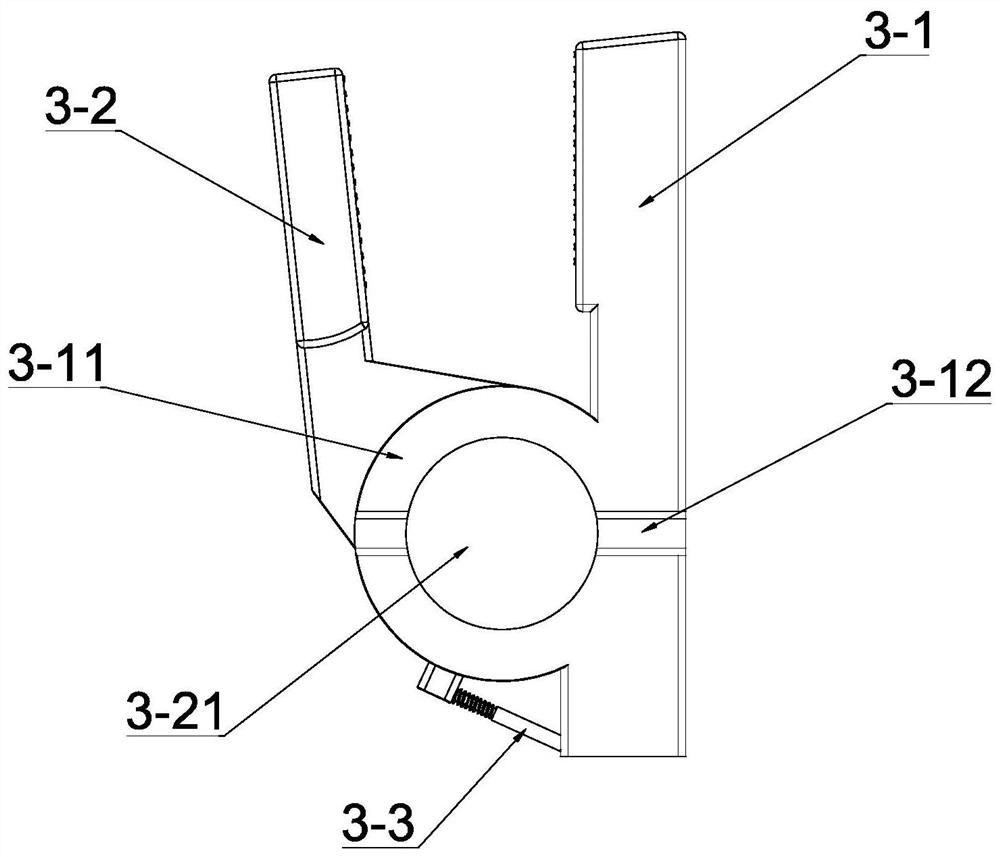
[0063] see Figure 12, the other structures in this embodiment are the same as those in Embodiment 1, the difference is that: the middle part of the first clamp body 3-1 is provided with a hinge seat 3-11, and the middle part of the second clamp body 3-2 The middle part is provided with a hinged shaft 3-21 that is rotatably matched with the hinged seat 3-11, and the elastic damper is a torsion spring 3-8, and the torsion spring 3-8 is sleeved on the hinged shaft 3-21. One end of the torsion spring 3-8 acts on the lower end of the first clamp body 3-1, and the other end acts on the lower end of the second clamp body 3-2. Through the above structure, the clamping function of the first clamp body 3-1 and the second clamp body 3-2 can be realized.


PUM


Abstract

The invention discloses a bearing end face warping preventing non-magnetic grinding device. The bearing end face warping preventing non-magnetic grinding device comprises a workbench arranged on a grinding machine rotating disc, at least three sliding grooves are formed in the workbench, the multiple sliding grooves are evenly distributed in the circumferential direction, the sliding grooves extend in the radial direction, each sliding groove is provided with an elastic damping clamping mechanism which is used for clamping a bearing sleeve ring and is in sliding fit with the corresponding sliding groove, and the workbench is composed of a double-layer structure and comprises a hard layer located on the upper layer and a soft base body located on the lower layer. By means of the bearing endface warping preventing non-magnetic grinding device, bearing warping deformation generated in the clamping process can be prevented, and the machining precision of the end faces of large or flexiblethin-wall bearings is further improved.

Description

technical field [0001] The invention relates to the technical field of bearing processing, in particular to a non-magnetic grinding device and method for preventing warpage of a bearing end face. Background technique [0002] The end face of the bearing is not only the installation datum of the bearing, but also one of the main technological datum faces of each grinding process. The accuracy of the end face directly affects the final quality of the bearing. Therefore, the end face of the bearing is usually required to have a high flatness. Due to its own structural reasons, large or flexible thin-walled bearings usually have end face warping after rough grinding and heat treatment, and the end face is usually ground by grinding and other means. , Improve the accuracy of the bearing end face. However, in actual processing, magnetic force is usually used to adsorb and fix the bearing on the workbench. Due to the low rigidity of large bearings or thin and flexible bearings, un...

Claims


Application Information

Patent Timeline
Patent Type & Authority Applications(China)
IPC IPC(8): B24B7/16B24B41/06B24B41/02
CPCB24B7/16B24B41/06B24B41/02
Inventor 刘晓初高伟林萧金瑞梁忠伟黄建枫朱锐
Owner GUANGZHOU UNIVERSITY
Learn More