The method of finding the center of the replaceable head cutter head

A cutter head and block alignment technology, which is applied in metal processing equipment, automatic control devices, metal processing machinery parts, etc., can solve the problem of difficulty in finding the center of replaceable cutter heads, and the method is simple, fast, and accurate. positive speed effect

Active Publication Date: 2022-08-02
CHENGDU QIPING TECH CO LTD
View PDF12 Cites 0 Cited by
  • Summary
  • Abstract
  • Description
  • Claims
  • Application Information

AI Technical Summary

Problems solved by technology

[0004] In view of the above-mentioned deficiencies in the prior art, the method for finding the center of the replaceable cutter head provided by the present invention solves the problem of difficulty in finding the center of the replaceable cutter head in the prior art

Method used


Image

  • The method of finding the center of the replaceable head cutter head
  • The method of finding the center of the replaceable head cutter head
  • The method of finding the center of the replaceable head cutter head

Examples


Embodiment Construction

[0022] The specific embodiments of the present invention are described below to facilitate the understanding of the present invention by those skilled in the art, but it should be clear that the present invention is not limited to the scope of the specific embodiments. These changes are obvious within the spirit and scope of the present invention defined and determined by the claims, and all creations utilizing the present concept are included in the protection list.

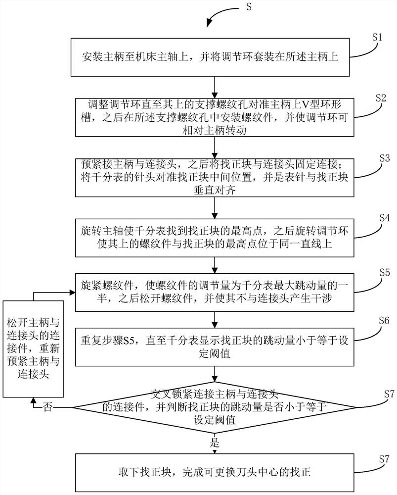
[0023] refer to figure 1 , figure 1 A flow chart showing the method of centering the interchangeable head cutter head; such as figure 1 As shown, the method includes steps S1 to S8.

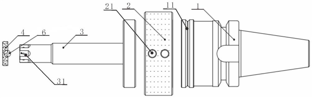
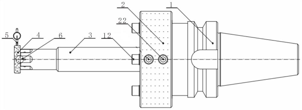
[0024] In step S1, install the main handle 1 on the main shaft of the machine tool, and set the adjusting ring 2 on the main handle 1; such as figure 2 and image 3 As shown, the connecting section of the main handle 1 and the main shaft of the machine tool is a cylindrical step, and a V-shaped annular groove 11 is provided on...


PUM


Abstract

The invention discloses a method for centering a replaceable head cutter head, which comprises the steps of installing a main handle on a machine tool spindle, an adjusting ring being rotatably mounted on the main shaft; fixedly connecting the main handle and the connecting head, and connecting the alignment block to the connecting head Fixed connection; align the needle of the dial indicator with the middle of the alignment block; rotate the main shaft to make the dial indicator find the highest point of the alignment block, and rotate the adjusting ring to align the threaded parts with the highest point of the alignment block; tighten the thread The adjustment amount of the threaded part is half of the maximum runout of the dial indicator, and the threaded part is loosened so that it does not interfere with the connector; repeat the previous step until the dial indicator shows that the runout of the alignment block is less than or equal to Set the threshold; cross-lock the connector connecting the main handle and the connector, and judge whether the runout of the alignment block is less than or equal to the set threshold, if so, go to the next step, otherwise loosen the connector between the main handle and the connector, and restart Pre-tighten the main shank and the connecting head, and return to the step of rotating the spindle; remove the alignment block to complete the alignment of the center of the replaceable cutter head.

Description

technical field [0001] The invention relates to a method for aligning the center of a cutter head, in particular to a method for aligning the center of a cutter head with an exchangeable head. Background technique [0002] At present, there are two common methods of aligning the center of the exchangeable head cutter on the market. The first is to directly align the outer circle of the cutting edge cutter head. This method is to operate on the cutter head after cutting edge. After cutting edge, the cutter head has a cutting function. The intermittent contact will cause cutting damage to the alignment instrument, and it is difficult to operate, and it is not easy to find the center point. [0003] The second is to process an alignment belt at a certain part of the tool bar, and confirm the center of the cutter head by aligning the center of the alignment belt; the alignment belt cannot be machined on the cutting edge of the cutter head, and can only deviate from the cutter. ...

Claims


Application Information

Patent Timeline
Patent Type & Authority Patents(China)
IPC IPC(8): B23Q15/22
CPCB23Q15/22
Inventor 陈自平付强
Owner CHENGDU QIPING TECH CO LTD
Why Eureka
Try Eureka