Alignment Fixture and Alignment Method for Complicated Housing Installation State

A technology of installation state and fixture, which is applied in the direction of manufacturing tools, workpiece clamping devices, etc., can solve the problems of complex shape anisotropy, the inability to form a part shape, and the inability to achieve alignment, etc., to improve alignment accuracy, The effect of reducing labor costs and eliminating human errors

Active Publication Date: 2021-05-04
XIAN AERO ENGINE CONTROLS
View PDF12 Cites 0 Cited by
  • Summary
  • Abstract
  • Description
  • Claims
  • Application Information

AI Technical Summary

Problems solved by technology

The existing alignment methods are only for regular parts. However, for shell parts with complex shapes and large structural anisotropy, alignment cannot be achieved by dividing the center or directly marking the shape of the part.
Since the part has been clamped and the positioning pin is blocked by the part, the method of aligning the positioning pin cannot be achieved.

Method used


Image

  • Alignment Fixture and Alignment Method for Complicated Housing Installation State
  • Alignment Fixture and Alignment Method for Complicated Housing Installation State
  • Alignment Fixture and Alignment Method for Complicated Housing Installation State

Examples


Embodiment

[0050]The correction method provided by the present invention is specifically:

[0051] A. Fixture design, different housings, positioning pins and pressing points are all different.

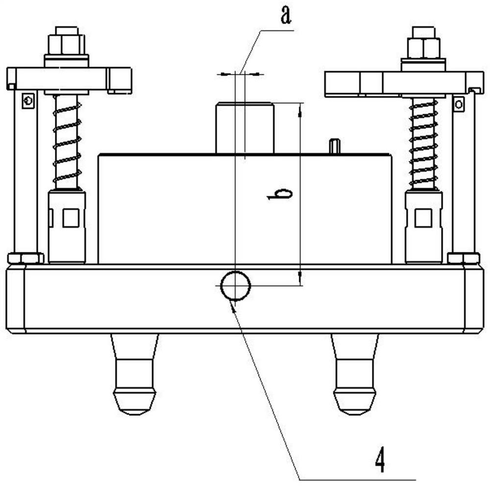
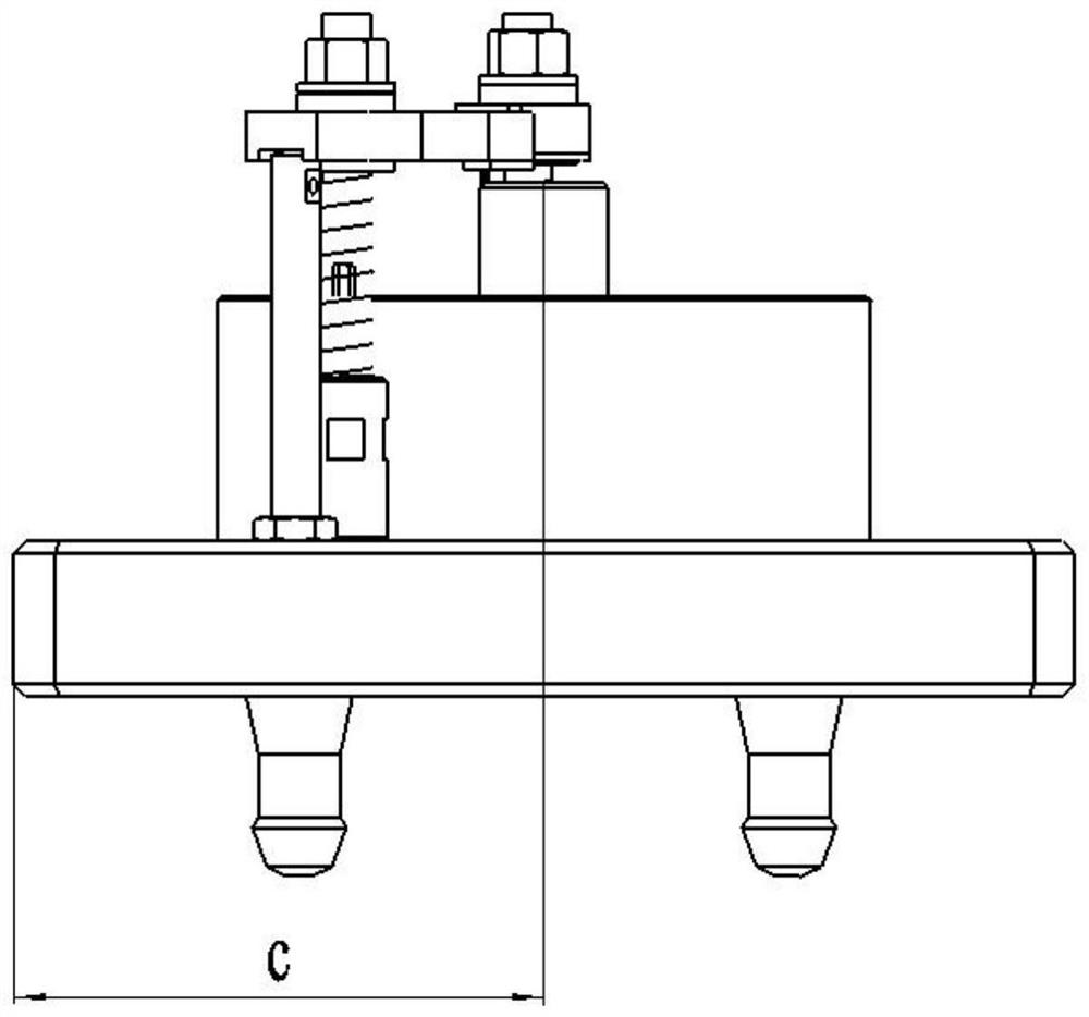
[0052] a. The fixture is designed for complex shells. The shell is clamped and positioned according to a positioning surface (1) and two positioning pins (2). The position size (67, 88) between the two positioning pins is based on the distance between the positioning holes of the parts set up;

[0053] b. Select one of the two positioning pins as the main positioning pin (3), and design an alignment hole (4) on the side of the fixture body. The distance between the alignment hole and the main positioning pin (130, 10, 120) is the absolute size. Change;

[0054] c. There is a clamping rivet (5) at the bottom of the fixture, and the position and size of the rivet are matched with the hole position of the workbench base;

[0055] B. Clamping parts

[0056] A fixed base is installed on the machi...


PUM


Abstract

The invention belongs to the field of mechanical processing, and relates to an aligning jig and an aligning method for a complex shell installation state. Align the positioning surface of the part; the auxiliary positioning pin and the main positioning pin which are respectively perpendicular to the positioning surface are arranged in parallel on the positioning surface; the side wall of the boss is provided with an alignment hole; the distance between the alignment hole and the main positioning pin is Constant; the lower surface of the fixture body is provided with clamping pull studs; the upper surface of the fixture body is provided with a pressure plate for fixing the parts to be aligned. The invention provides an aligning jig and an aligning method in a complex shell installation state with strong versatility, excellent aligning speed and improved aligning accuracy.

Description

technical field [0001] The invention belongs to the field of mechanical processing, and relates to an alignment jig and an alignment method, in particular to an alignment jig and an alignment method in a complex shell installation state. Background technique [0002] In the part alignment process, the existing part alignment method detects the part through an online measuring device, so as to obtain the zero point center. The existing alignment methods are only for regular parts. However, for shell parts with complex shapes and large structural anisotropy, alignment cannot be achieved by dividing or directly marking the shape of the parts. Since the parts have been clamped and the positioning pins are blocked by the parts, the method of aligning the positioning pins cannot achieve alignment. Contents of the invention [0003] In order to solve the above-mentioned technical problems in the background technology, the present invention provides an alignment jig and alignment...

Claims


Application Information

Patent Timeline
Patent Type & Authority Patents(China)
IPC IPC(8): B25B11/00
CPCB25B11/00
Inventor 张童窦媛李峰宋文田东缙陈颢
Owner XIAN AERO ENGINE CONTROLS
Why Eureka
Try Eureka