Bearing member
A bearing component and shaft hole technology, applied in bearing components, bearings, crankshaft bearings, etc., can solve problems such as sintering and increased friction, and achieve the effects of improving heat dissipation, thermal conductivity, and suppressing high temperature.
- Summary
- Abstract
- Description
- Claims
- Application Information
AI Technical Summary
Problems solved by technology
Method used
Image
Examples
no. 1 approach
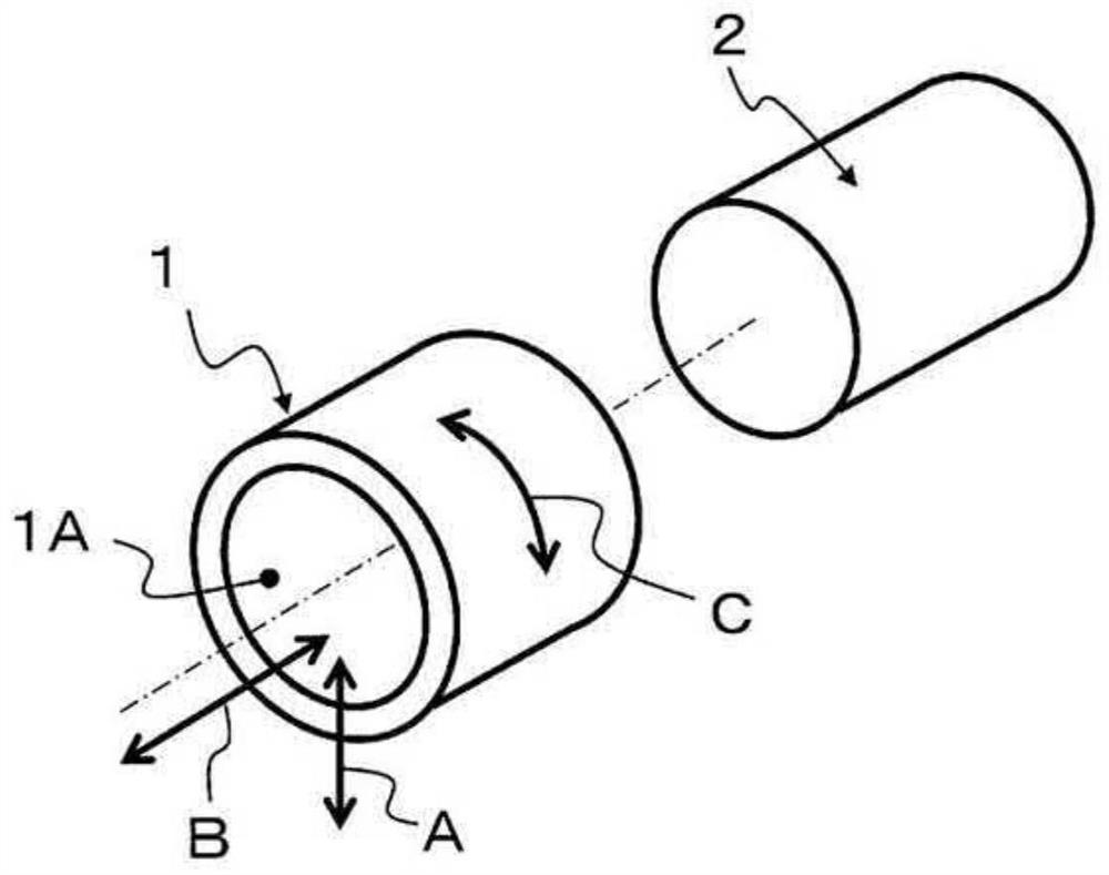
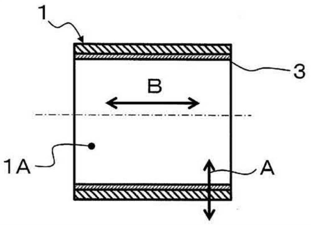
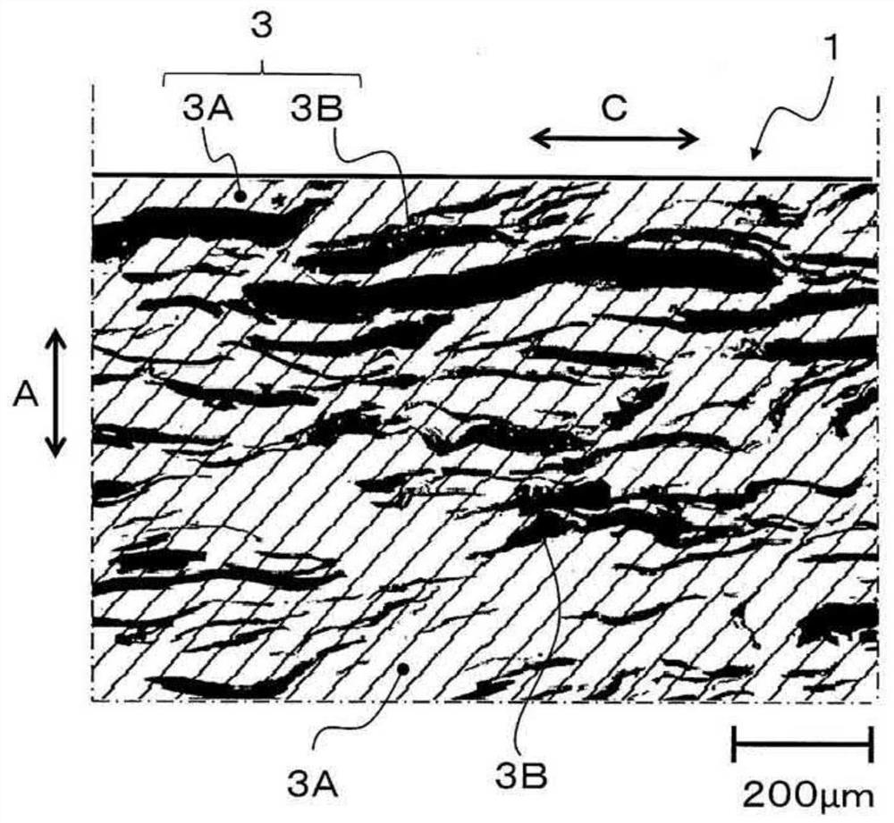
[0020] figure 1 and figure 2 The bearing component 1 shown has a coating 3 on the inner peripheral surface of the shaft bore 1A of the mounting shaft body 2 . Such as image 3 As shown, the covering layer 3 is composed of a metal base material 3A and a thermally conductive material 3B dispersed in the base material 3A and having a relatively higher thermal conductivity than the base material 3A.
[0021] Such as Figure 4 As shown, the heat conductive material 3B is configured such that the lengths Lb and Lc in the directions (B and C) along the surface of the coating layer 3 are longer than the length La in the thickness direction A of the coating layer 3 . The directions (B and C) along the surface of the covering layer 3 are directions along a surface (cylindrical curved surface) including the axial direction B of the shaft hole 1A and the circumferential direction C of the shaft hole 1A. In short, the thermally conductive material 3B is a flat structure extending alon...
Embodiment 1
[0066] In Example 1, the ratio of the length in the axial direction to the length in the circumferential direction (Lb:Lc) of the thermally conductive material was set to 1:1, but compared with Comparative Example 1, the thermal conductivity was significantly higher, and the temperature of the sliding part was lower, confirming that Effectiveness of thermally conductive materials.
[0067] In Examples 2, 4 and 6, the ratio (Lb:Lc) of the length in the axial direction to the length in the circumferential direction of the thermally conductive material is set to 1:2, thereby obtaining high thermal conductivity and low thermal conductivity compared with Example 1. sliding part temperature. Thus, the effectiveness of the bearing component by increasing the flatness of the thermally conductive material in the covering layer was confirmed.
Embodiment 3
[0068] In Example 3, the ratio of the length in the axial direction to the length in the circumferential direction (Lb:Lc) of the thermally conductive material was set to 1:4, which resulted in the highest thermal conductivity among the examples and the result that the temperature of the sliding part was low. From this, it was confirmed that the length of the thermally conductive material in the bearing member in the circumferential direction is three times or more than the length in the axial direction.
[0069]In addition, both Examples 4 and 6 obtained the result that high thermal conductivity and low sliding part temperature were obtained by changing the distribution density of the thermal conductive material in the thickness direction of the coating layer. In particular, in Example 4, that is, in Example 4 in which the distribution density of the heat-conducting material is changed from dense to sparse in the direction from the surface of the covering layer toward the cent...
PUM
| Property | Measurement | Unit |
|---|---|---|
| Vickers hardness | aaaaa | aaaaa |
| surface roughness | aaaaa | aaaaa |
| thickness | aaaaa | aaaaa |
Abstract
Description
Claims
Application Information
 - R&D
- Intellectual Property
- Life Sciences
- Materials
- Tech Scout
- Unparalleled Data Quality
- Higher Quality Content
- 60% Fewer Hallucinations
Browse by: Latest US Patents, China's latest patents, Technical Efficacy Thesaurus, Application Domain, Technology Topic, Popular Technical Reports.
© 2025 PatSnap. All rights reserved.Legal|Privacy policy|Modern Slavery Act Transparency Statement|Sitemap|About US| Contact US: help@patsnap.com


