Rotary press die

一种旋转模具、冲压模具的技术,应用在成型工具、制造工具、运输和包装等方向,能够解决无法进行修正、难以形成直径变化复杂形状等问题,达到高硬度、良好润滑性、确保深度尺寸的效果

Active Publication Date: 2020-12-25
YOURBUSINESS
View PDF4 Cites 0 Cited by
  • Summary
  • Abstract
  • Description
  • Claims
  • Application Information

AI Technical Summary

Problems solved by technology

However, since there is no place for adjustment of this rotary punching die, it is almost impossible to correct it except for grinding the cylindrical rotary cam and the cylindrical groove.
[0008] In addition, rotary press dies using cylindrical rotary cams have problems such as difficulty in forming complex shapes with diameter changes other than cylindrical ones, and many steps required to form oil grooves for lubrication.

Method used


Image

  • Rotary press die
  • Rotary press die
  • Rotary press die

Examples


Embodiment 1

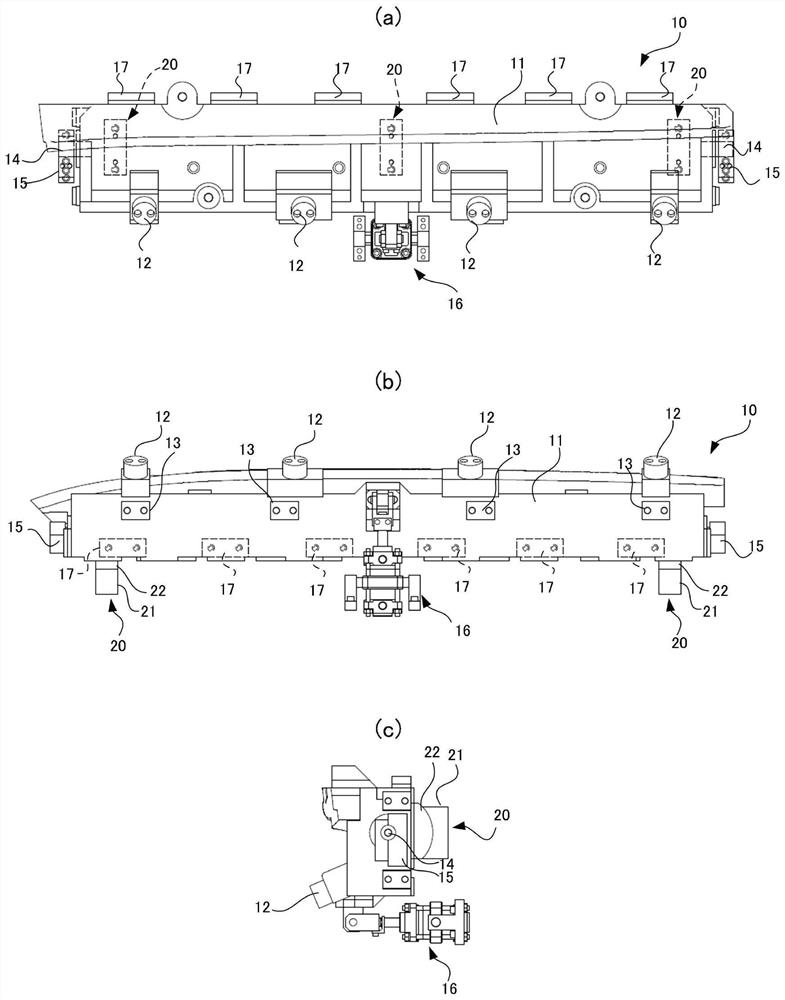
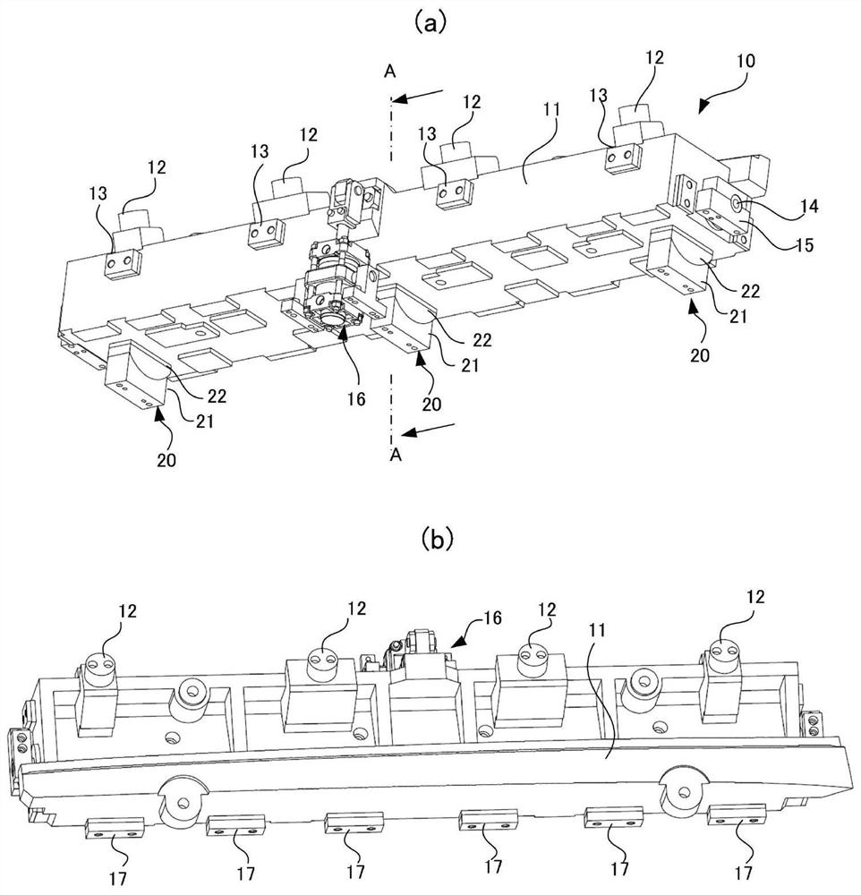
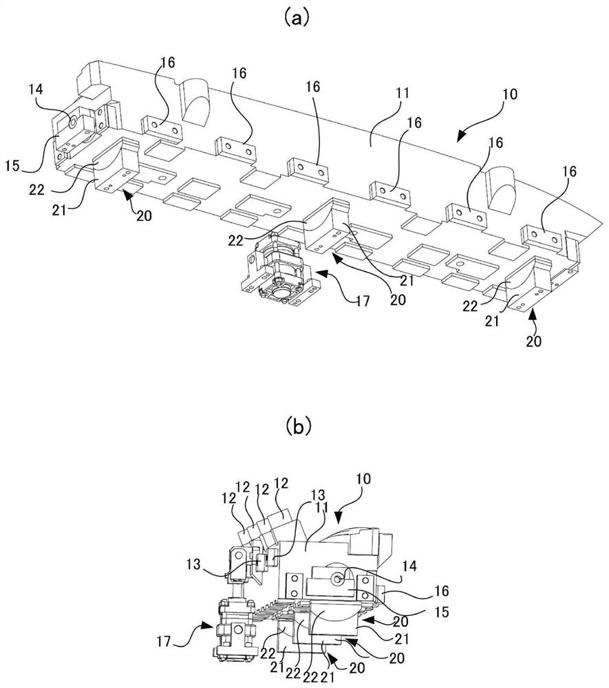
[0042] A first embodiment of the present invention will now be described. figure 1 The rotary die of the rotary press die according to the first embodiment of the present invention is shown, (a) is a plan view of the rotary die, (b) is a front view of the rotary die, and (c) is a side view of the rotary die. figure 2 The rotary die of the rotary punching die according to the first embodiment of the present invention is shown, (a) is a side view of the rotary die, and (b) is a side view of the rotary die in a different direction from that of (a). image 3 Shows the same rotary stamping die, (a) is a side view of the rotary stamping die, (b) is a side view of the rotary stamping die in a different direction from Figure (a), Figure 4 shows the construction of a rotary stamping die figure 2 Cross-sectional view of line AA in (a).

[0043] Such as Figure 4 , Figure 5 As shown, the rotary stamping die (10) fixes the rotatable rotary die (11) on the fixed base (31) through ...

Embodiment 2

[0073] A rotary press die according to a second embodiment of the present invention will now be described. Figure 8 The rotary die of the rotary press die according to the second embodiment of the present invention is shown, (a) is a cross-sectional view of the rotary press die in the state where pressurization is completed, and (b) is a cross-section of the rotary press die with the work plate removed picture.

[0074] The rotary press die (40) of this embodiment forms a working plate P whose shape is different from that of the first embodiment. Therefore, the shape of the rotating die (41) of the rotary stamping die (40), the shape of the horizontally moving cam (52), the vertically moving cam (53), the fixed die (54), etc. are different from those of the first embodiment, but basically Same construction.

[0075] In this embodiment, the rotary block (20) of the rotary press die in the first embodiment can be used for the rotary die (41). That is to say, in this embodime...


PUM


Abstract

The objective of the present invention is to provide a rotary press die with which it is possible to set a center of rotation of a rotary die with high accuracy. The rotary press die is provided witha rotary die for forming a negative angle portion in a plate-shaped workpiece, and a fixed die which is disposed outside the rotary die to form a molded portion other than the negative angle portion in the workpiece, wherein the rotary die is a press molding die which pivots about a pivot axis Or when the workpiece is to be removed, and which is formed to be capable of being retracted toward the inside of the fixed die. A pivot block holding the rotary die in such a way as to be capable of pivoting about the pivot axis Or is provided between a fixed base on which the rotary die is placed, andthe rotary die, and the pivot block consists of a fixed piece which is disposed on the fixed base and which is provided with a concave sliding surface centered at the pivot axis Or, and a movable piece which is disposed in the rotary die, and which is provided with a convex sliding surface capable of sliding about the pivot axis Or along the concave sliding surface, wherein the concave sliding surface and the convex sliding surface have an opening angle from the pivot axis Or at least equal to 80 degrees and at most equal to 100 degrees.

Description

technical field [0001] The present invention relates to a rotary punching die, which punches a plate-shaped work plate by rotating a cam to form a negative corner. Background technique [0002] A conventional rotary press die is a cylindrical rotary cam having a cylindrical rotating body. This type of rotary stamping die is widely used because it can form negative corners at the ends of body panels. [0003] The cylindrical rotary cam is generally a cylindrical member made of cast iron, and is rotated by forming a cylindrical groove in a cast iron casing. A negative corner is formed by pressing on the working plate between a part of the cylindrical rotating cam and another die, and the processed working plate can be easily removed by rotating the cylindrical rotating cam and moving to the housing. [0004] However, such a cylindrical rotary cam made of cast iron has a problem that processing is difficult at the time of manufacture. In particular, the large cylindrical rot...

Claims


Application Information

Patent Timeline
Patent Type & Authority Applications(China)
IPC IPC(8): B21D37/08B21D5/01
CPCB21D19/086B21D53/88B21D37/12B21D28/32B21D37/10B21D5/01B21D37/01B21D37/08
Inventor 木下忠俊
Owner YOURBUSINESS
Why Eureka
Try Eureka