Laser control device

一种控制装置、激光器的技术,应用在仪器、光束源、光学记录头等方向,能够解决峰值保持电路检波效率下降、难以正确地检测峰值输出电平和偏置输出电平、监视器输出信号迟缓等问题

Inactive Publication Date: 2005-07-13
PANASONIC CORP
View PDF0 Cites 0 Cited by
  • Summary
  • Abstract
  • Description
  • Claims
  • Application Information

AI Technical Summary

Problems solved by technology

[0012] However, in CD-RW and CD-RW drives, the so-called Double-speed recording, etc., are recording data on the optical disc at high speed. Correspondingly, the modulation speed of the laser needs to be increased. However, in order to control the laser power under such high-speed modulation, in the conventional structure, it is necessary to separately Detection bias power P B , erase power P E and peak power P P Therefore, devices capable of high-speed response are required in the monitor circuit, bottom peak hold circuit, and peak hold circuit, and there is a problem of causing cost increase
[0013] That is, even if the laser is modulated at high speed, and the high-speed modulated light is incident on the photodiode for monitoring, if a device with a low response speed is used in the photodiode or the monitor circuit, a signal delay or sluggishness will occur due to this. , thus also producing sluggishness in the monitor output signal, such as image 3 As shown, there is a problem that the optical output waveform cannot be accurately reflected, or even if the output signal of the monitor circuit becomes high speed, the detection efficiency of the bottom peak hold circuit and the peak hold circuit decreases as the signal becomes high speed, and there is a problem that Difficulty in correctly detecting its peak output level and offset output level
In addition, if these problems are to be avoided, it is necessary to use devices capable of high-speed response in the monitor circuit, bottom peak hold circuit, and peak hold circuit, so there is a problem of cost increase

Method used


Image

  • Laser control device
  • Laser control device
  • Laser control device

Examples


Embodiment Construction

[0047] (Embodiment 1)

[0048] Next, a laser control device according to an embodiment of the present invention will be described.

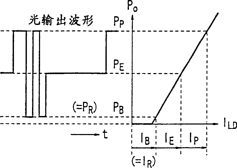
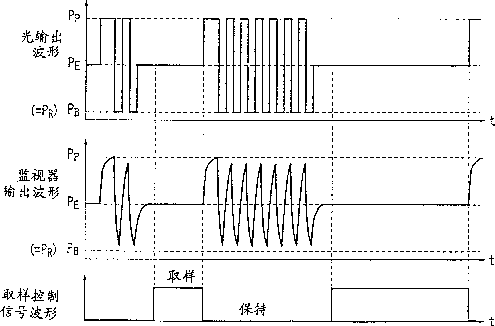
[0049] This embodiment 1 corresponds to the invention described in the first and second aspects of the present invention. The bottom peak power is controlled using the APC value at the time of reproduction immediately before recording, and the erasing power is controlled by a sample holder because the period is relatively long. After the power is detected, the APC control is performed directly, and the peak power is controlled according to the control value of the erasing power.

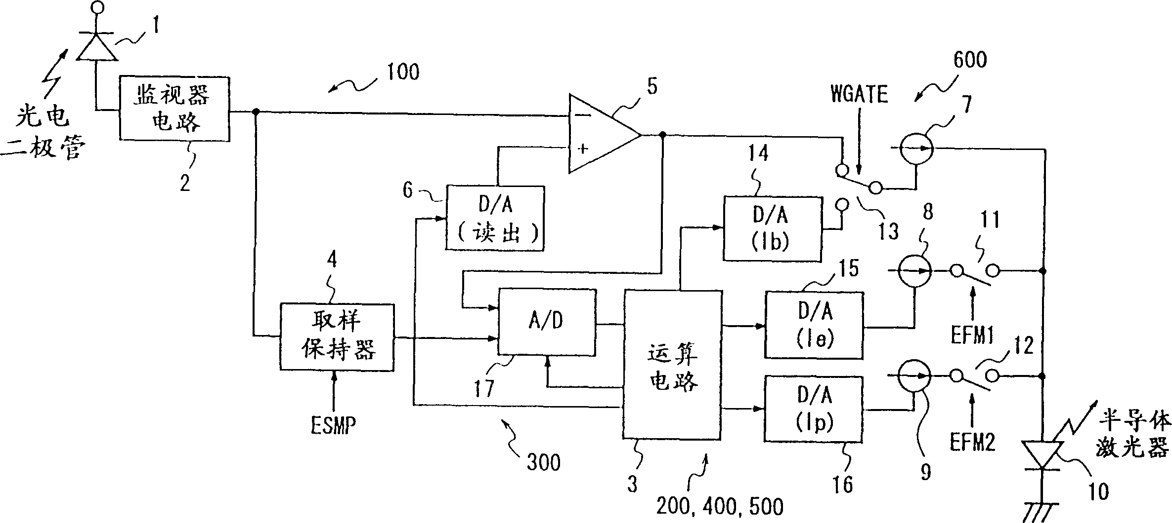
[0050] figure 1 A laser control device according to Embodiment 1 of the present invention is shown. exist figure 1 Among them, 10 is a semiconductor laser that irradiates laser light to the optical disk, 1 is a photodiode that receives light irradiated by the semiconductor laser 10, and 2 is a monitor circuit (current-voltage conversion device, current-voltage conv...


PUM


Abstract

When the laser modulation speed is high, it is difficult to accurately detect the peak power and bias power for laser power control. The present invention achieves a laser control device that solves the above problems. In this laser control device, the bias power current I b According to the calculation value of the calculation circuit 3, the reproduction power current I passing through the servo amplifier 5 during reproduction immediately before recording is r The control value is controlled due to the erase power P E It is a relatively long period, so the power is detected by the sample and hold circuit 4, and the erasing power current I is controlled by the arithmetic circuit 3 e , peak power P P According to the calculation value of the calculation circuit 3, through the above-mentioned erasing power current I e control, thereby eliminating the need for bottom and peak hold circuits, and also for high-speed performance in the photodiode and monitor circuits.

Description

technical field [0001] The present invention relates to a laser control device, and in particular to a device capable of stably controlling optical power even when the output light is modulated at high speed during high-speed recording in a device for controlling the power of a semiconductor laser. It is used in optical recording and reproducing devices. Background technique [0002] Semiconductor lasers are used in optical pickups of optical recording and reproducing devices such as CD players, rewritable CD-R drives, and rewritable CD-RW drives. Since the power of semiconductor lasers changes with temperature or time (life) Therefore, it is necessary to perform power control for power stabilization when used as a light source of a device for recording and reproducing on an optical recording medium such as an optical disc. [0003] Details of such a conventional semiconductor laser power control device are described in Japanese Unexamined Patent Publication No. 1-2042242. ...

Claims


Application Information

Patent Timeline
Patent Type & Authority Patents(China)
IPC IPC(8): G11B7/006G11B7/1263
CPCG11B7/0062G11B7/1263
Inventor 宫川智真锅和男今井则夫
Owner PANASONIC CORP
Why Eureka
Try Eureka