
Image processing system and markers

A technology of image processing and markers, applied in image data processing, image analysis, instruments, etc., can solve time-consuming and labor-intensive problems

Active Publication Date: 2021-08-31
TOSHIBA ELEVATOR KK
View PDF5 Cites 0 Cited by
  • Summary
  • Abstract
  • Description
  • Claims
  • Application Information

AI Technical Summary

Problems solved by technology

However, in the case of this method, a display device for displaying a captured image at the time of installation is required, and the detection area is manually designated, so it is inconvenient that it takes time and effort.

Method used


Image

  • Image processing system and markers
  • Image processing system and markers
  • Image processing system and markers

Examples


no. 1 Embodiment approach >

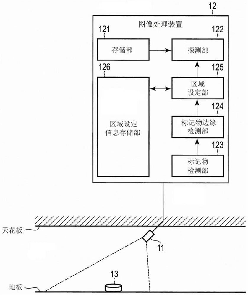
[0033] figure 1 It is a diagram showing a schematic configuration example of the image processing system according to the first embodiment.

[0034] Such as figure 1 As shown, the image processing system includes a camera 11 (also referred to as an "imaging unit"), an image processing device 12, and markers 13. A system of people, objects, etc.

[0035] The camera 11 is, for example, a small surveillance camera such as a vehicle-mounted camera, has a wide-angle lens, and can continuously capture images of several frames (for example, 30 frames / second) per second.

[0036] Each image (video) captured continuously by the camera 11 is analyzed and processed in real time by the image processing device 12 . Specifically, the image processing device 12 detects (the movement of) a person, an object, etc. based on a change in the brightness value of the image in a specific area.

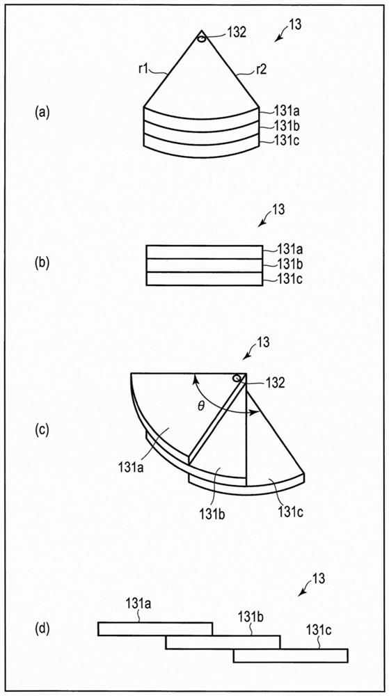
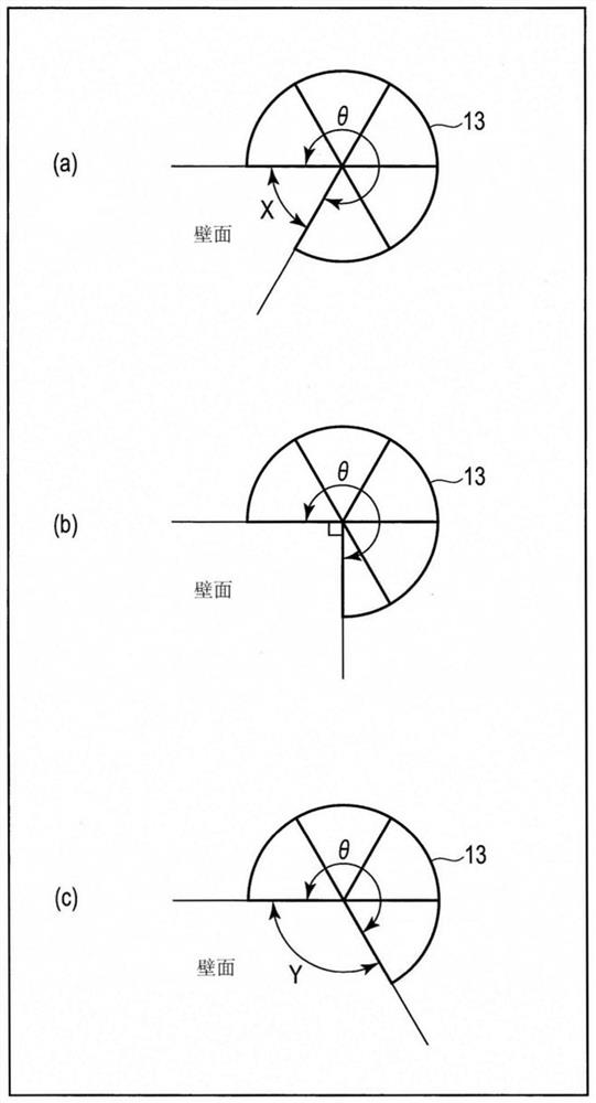
[0037] The marker 13 is used to set a detection area where the image processing device 12 can detect ...

no. 2 Embodiment approach >

[0096] Next, a second embodiment will be described. In the second embodiment, if Figure 19 As shown, the image processing device 12 is different from the first embodiment in that a marker designation direction determination unit 127 is further provided. In addition, the same code|symbol is attached|subjected to the part which has the same function as 1st Embodiment, and the detailed description is abbreviate|omitted.

[0097] In addition, in this embodiment, it is assumed not to use Figure 14 , 15 markers 13 painted in a single color as shown, while using Figure 16 , 17 Shown is the case where the markers 13 of the inner circle and the outer circle are painted with the first and second colors, respectively.

[0098] The marker designation direction determination unit 127 specifies the place where the detection area is set based on the color of the inner circle (or the color of the outer circle) of the marker 13 . More specifically, the marker specifying direction dete...


PUM


Abstract

The present invention provides an image processing system and a marker capable of setting highly accurate detection regions even with complex shapes. An image processing system according to an embodiment includes: an imaging unit that captures a subject including one or more markers for setting a detection area capable of detecting the movement of a person or an object; Detecting in the captured image one or more markers that can rotate in the left and right directions with the rotation fulcrum as a reference and have two sides extending from the rotation fulcrum; an area setting unit that sets the area including each two sides Defined as a detection area, each of which belongs to two sides constitutes one or more markers detected by the detection unit; and a detection unit, which detects the movement of a person or object within the detection area set by the area setting unit.

Description

[0001] This application is based on Japanese Patent Application No. 2017-058801 (filing date: 3 / 24 / 2017), and enjoys priority based on this application. This application incorporates the entire contents of this application by reference thereto. technical field [0002] Embodiments of the present invention relate to an image processing system and markers. Background technique [0003] In general, when installing an image sensor that detects the movement of a person or an object from an image captured by a camera, it is necessary to set a detection area capable of detecting the movement of the person or object. [0004] As a method of setting the detection area, there is, for example, a method of displaying a captured image on a display device at the time of installation and manually designating (setting) the detection area on the display device. However, in the case of this method, a display device for displaying a captured image at the time of installation is required, and ...

Claims


Application Information

Patent Timeline
Patent Type & Authority Patents(China)
IPC IPC(8): G06T7/73
CPCG06T7/73
Inventor 横井谦太朗野田周平田村聪木村纱由美
Owner TOSHIBA ELEVATOR KK
Learn More