Rotary compressor, refrigeration cycle device, and method for manufacturing rotary compressor

A technology of a rotary compressor and a manufacturing method, which is applied in the direction of rotary piston machines, rotary piston pumps, machines/engines, etc., and can solve problems such as vane spring offset and inability to set vane springs with high precision

Pending Publication Date: 2022-06-21
MITSUBISHI ELECTRIC CORP
View PDF1 Cites 0 Cited by
  • Summary
  • Abstract
  • Description
  • Claims
  • Application Information

AI Technical Summary

Problems solved by technology

Therefore, if the spring guide is fixed to the airtight container, the position of the leaf spring may be shifted from the normal position due to the deformation of the airtight container due to the internal pressure, and the leaf spring cannot be installed with high precision.

Method used


Image

  • Rotary compressor, refrigeration cycle device, and method for manufacturing rotary compressor
  • Rotary compressor, refrigeration cycle device, and method for manufacturing rotary compressor
  • Rotary compressor, refrigeration cycle device, and method for manufacturing rotary compressor

Examples


Embodiment approach 1

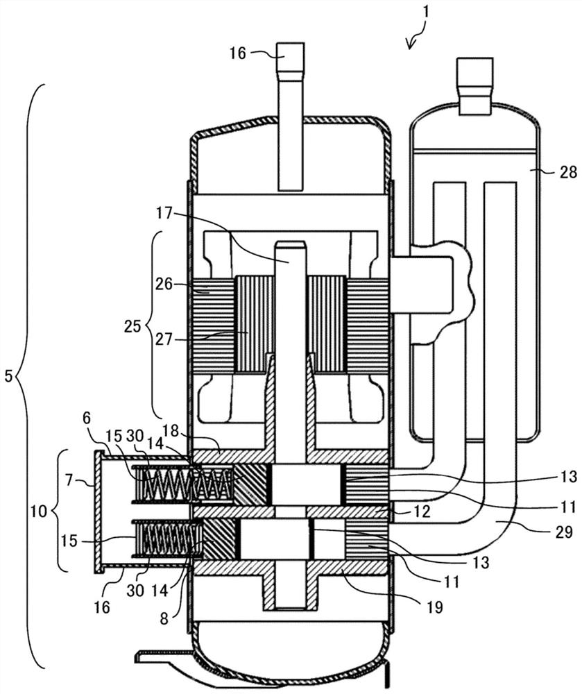
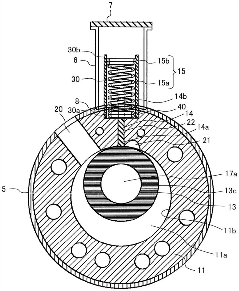
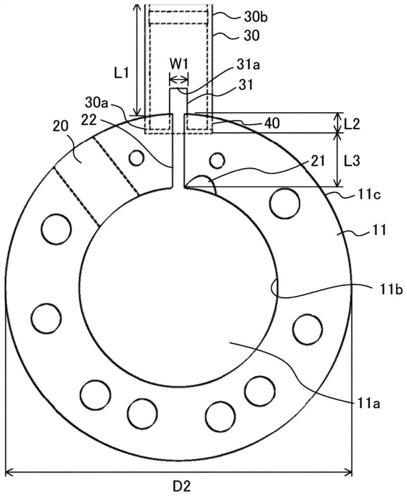
[0024] figure 1 It is a cross-sectional view showing a schematic configuration of the rotary compressor according to the first embodiment. figure 2 It is an enlarged transverse cross-sectional view of a compression mechanism part in the rotary compressor according to the first embodiment. image 3 It is an enlarged view which shows the connection structure of the spring guide of the rotary compressor which concerns on Embodiment 1, and a cylinder block. Wherein, in this specification, when referred to as "radial direction", "circumferential direction" and "axial direction" unless otherwise specified, they refer to the "radial direction", "circumferential direction" and "axial direction" of the cylinder, respectively. Axial".

[0025] The rotary compressor 1 includes, inside the airtight container 5 , an electric element 25 , a compression element 10 that compresses the refrigerant, and a rotating shaft 17 that transmits the driving force of the electric element 25 to the co...

Embodiment approach 2

[0116] The second embodiment relates to a refrigeration cycle apparatus including the rotary compressor 1 of the first embodiment.

[0117] Figure 11 It is a figure which shows the refrigerant circuit of the refrigeration cycle apparatus which concerns on Embodiment 2.

[0118] The refrigeration cycle apparatus 50 includes the rotary compressor 1 of the first embodiment, a condenser 51 , an expansion valve 52 serving as a decompression device, and an evaporator 53 . The gas refrigerant discharged from the rotary compressor 1 flows into the condenser 51, exchanges heat with the air passing through the condenser 51, becomes a high-pressure liquid refrigerant, and flows out. The high-pressure liquid refrigerant flowing out of the condenser 51 is decompressed by the expansion valve 52 to become a low-pressure gas-liquid two-phase refrigerant, and flows into the evaporator 53 . The low-pressure gas-liquid two-phase refrigerant flowing into the evaporator 53 exchanges heat with t...


PUM


Abstract

This rotary compressor is provided with: a sealed container; an annular cylinder housed in the sealed container; a rotary piston that eccentrically rotates along the inner circumferential surface of the cylinder; a vane that reciprocates in a vane groove provided in the cylinder in the radial direction; a vane spring that urges the vane so that the tip of the vane comes into contact with the rotary piston; and a cylindrical spring guide to which the leaf spring is fixed. The spring guide is provided so as to penetrate the sealed container, and one end of the spring guide is fixed to a fixing recess formed in the outer peripheral surface of the cylinder.

Description

technical field [0001] The present invention relates to a rotary compressor used in a refrigeration cycle of an air conditioner, a refrigerator, a refrigerator, or the like, a refrigeration cycle device, and a method for producing the rotary compressor. Background technique [0002] The rotary compressor includes an annular cylinder housed in an airtight container, a rotary piston eccentrically rotated in the cylinder, and vanes slidably arranged in vane grooves provided in the cylinder. The vane is urged by the vane spring, and the vane tip portion is always in contact with the rotary piston, and the space inside the cylinder is divided into a low-pressure space and a high-pressure space. Then, by eccentric motion of the rotary piston in the cylinder, the volume of the low-pressure space is reduced to become a high-pressure space, and the refrigerant sucked into the cylinder is compressed. [0003] In such a hermetic compressor, the leaf spring that urges the vanes is acco...

Claims


Application Information

Patent Timeline
Patent Type & Authority Applications(China)
IPC IPC(8): F04C18/356
CPCF04C18/356F04C2240/80F16F1/02
Inventor 五前尚久长泽宏树辰己胜俊滨田亮塚本拓真
Owner MITSUBISHI ELECTRIC CORP
Why Eureka
Try Eureka