
Composite Air Tank

A technology of composite materials and air storage tanks, which is applied in the field of composite material air storage tanks, can solve the problems of axial and radial winding, radial winding cannot strengthen water discharge holes, and axial winding cannot be carried out, so as to achieve the effect of ensuring safety strength

Active Publication Date: 2022-06-24
DONGFENG COMML VEHICLE CO LTD
View PDF11 Cites 0 Cited by
  • Summary
  • Abstract
  • Description
  • Claims
  • Application Information

AI Technical Summary

Problems solved by technology

[0005] Although the air storage tanks involved in CN209386002U, CN109253387A and CN107893905A are made of composite materials to achieve partial weight reduction, the water discharge pipe joints are arranged at the bottom of the cylinder body, which interferes with the winding route of the outer layer, so that the winding can only be wound in the radial direction. It does not wrap the end caps on both sides, the strength of the end caps cannot be guaranteed, and the connection strength between the end caps and the cylinder body will also be weak
The disadvantages are: 1. The water discharge hole is located at the bottom of the middle of the barrel, which interferes with the winding route of the outer layer. It cannot be wound axially, and the radial winding cannot strengthen the side of the water discharge hole. It is even necessary to cut the fibers near the water discharge hole to avoid interference. 2. The water discharge hole is close to the welding line of the inner tank, resulting in weakening of the strength near the welding line, and the risk of failure is extremely high; 3. The vent holes on both sides are directly placed on the plastic inner tank, and cannot Reinforced by filament winding, weak at the end cap
[0007] Because the vehicle air reservoir is a safety part directly responsible for vehicle braking, which is related to driving safety, none of the above patents can achieve complete axial and radial winding for the cylinder body, and cannot achieve full coverage, and there are great hidden dangers in terms of safety.

Method used


Image

  • Composite Air Tank
  • Composite Air Tank
  • Composite Air Tank

Examples


Embodiment 1

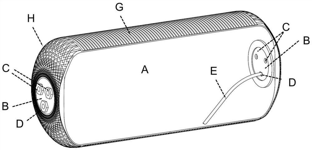
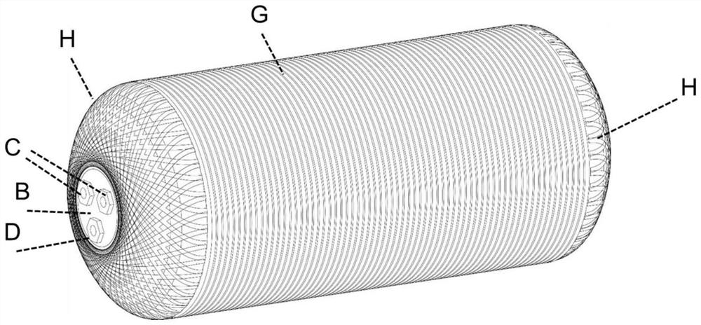
[0029] like Figure 1-7 As shown in the figure, in a composite air storage cylinder of the present invention, inserts B are arranged at both ends of the inner tank A, and an exhaust pipe joint C and a drain pipe joint D are arranged on the insert B, and the internal drain pipe E is connected to the drainage pipe. On the pipe joint D, the end of the inner drain pipe E is connected to the bottom of the air storage cylinder, and the outer layer is a fiber resin composite winding layer, which includes an axial winding layer H and a radial winding layer G (that is, axial winding and radial winding).

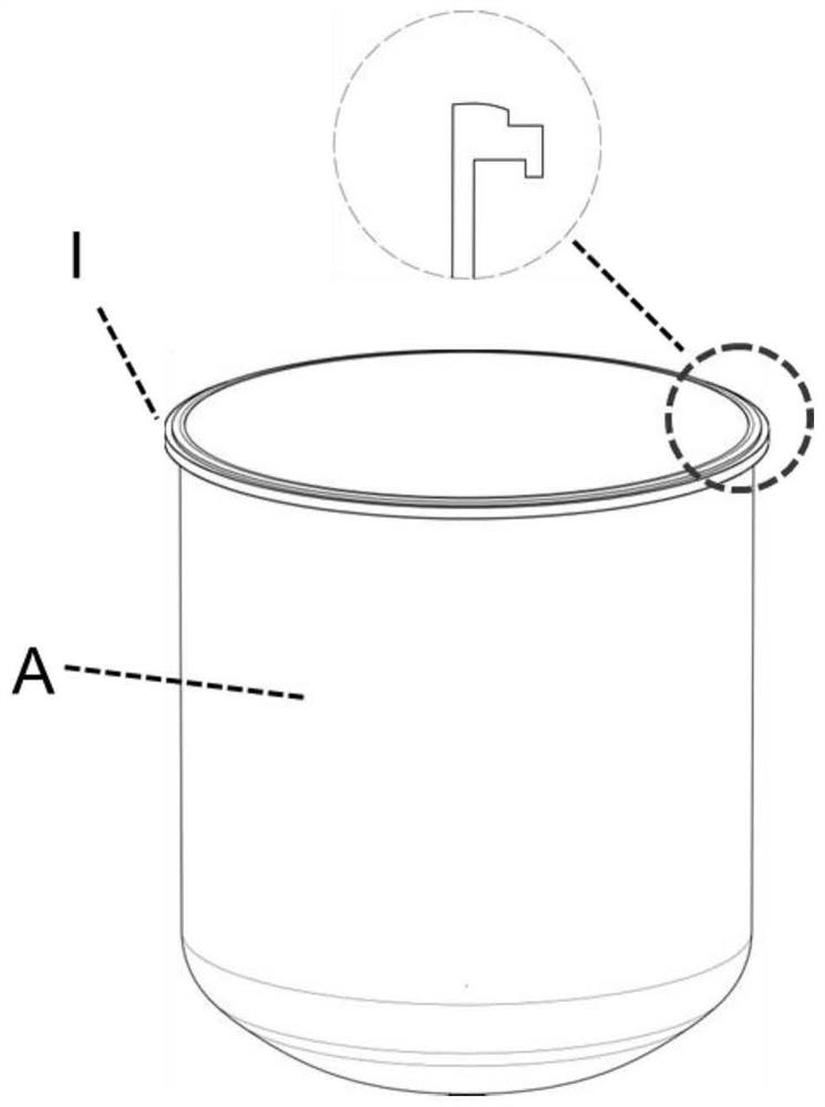
[0030] In this embodiment, three threaded holes are preset on the insert B, such as figure 2 The equiangular arrangement is shown, the insert B is embedded in the mold in advance, and injection molded together with the inner tank A. The material of the inner tank A is nylon 66+GF33 material, such as image 3 As shown, the welding boss I in the inner pot A is arranged to the outside...

Embodiment 2

[0035] A composite air storage cylinder, inserts B are arranged on both ends of the inner bladder A, an exhaust pipe joint C and a drain pipe joint D are arranged on the insert B, and the internal drain pipe E is connected to the drain pipe joint D. The end of the drain pipe E is connected to the bottom of the air storage cylinder, and the outer layer is a fiber resin composite winding layer. The fiber resin composite winding layer includes an axial winding layer H and a radial winding layer G (ie, axial winding and radial winding are adopted).

[0036] In this embodiment, three threaded holes are preset on the insert B, such as figure 2 The equiangular arrangement is shown, the insert B is embedded in the mold in advance, and injection molded together with the inner tank A. The material of the inner tank A is nylon 6+GF25 material, combined with Image 6 , the welding boss I in the inner tank is arranged inward.

[0037] The inner tank A consists of two halves. The two halv...

Embodiment 3

[0041] A composite air storage cylinder, inserts B are arranged on both ends of the inner bladder A, an exhaust pipe joint C and a drain pipe joint D are arranged on the insert B, and the internal drain pipe E is connected to the drain pipe joint D. The end of the drain pipe E is connected to the bottom of the air storage cylinder, and the outer layer is a fiber resin composite winding layer. The fiber resin composite winding layer includes an axial winding layer H and a radial winding layer G (ie, axial winding and radial winding are adopted).

[0042] In this embodiment, three threaded holes are preset on the insert B, such as figure 2 The equiangular arrangement is shown, the insert B is embedded in the mold in advance, and blow-molded together with the inner tank A, and the material of the inner tank A is PE material. The surface of the inner tank A is polished with 800-grit sandpaper, and then the surface of the inner tank is filament wound. In this embodiment, the mater...


PUM


Abstract

The invention relates to a composite material air storage cylinder. The air storage tank includes an inner tank, inserts are arranged at the ends of both sides of the inner tank, exhaust pipe joints and drain pipe joints are arranged on the inserts on both sides, internal drain pipes are connected to the drain pipe joints on both sides, and the internal The end of the drain pipe is connected to the bottom of the inner tank; the outer layer of the inner tank is provided with a fiber resin composite winding layer, and the fiber resin composite winding layer includes an axial winding layer and a radial winding layer. The present invention realizes the full coverage of the radial and axial winding of the barrel body; in addition, the drain hole and vent hole joints of the present invention are arranged on the aluminum alloy insert at the end, except that the insert itself has better strength as a metal part , The insert can also be covered by the projection of the axial winding along the axis of the cylinder body, which ensures the safety strength of both sides of the air storage cylinder.

Description

technical field [0001] The invention relates to the technical field of auto parts, in particular to a composite material air storage cylinder. Background technique [0002] Existing air storage tanks for vehicles are mostly made of steel or aluminum alloy materials. The former has a high material density, which does not conform to the trend of lightweight automobiles, and the interior needs to be treated with anti-rust surface; Metal-like materials, the material density is still slightly larger. [0003] The existing vehicle air intake drying equipment cannot completely dehumidify, so that the air storage tank will accumulate water inside after long-term operation, affecting the work efficiency of parts and the safety of use in winter, so regular drainage is required. However, due to gravity flow, the existing air storage cylinder arranges the drain valve at the bottom of the cylinder body. [0004] Filament winding is a widely used composite material reinforcement technol...

Claims


Application Information

Patent Timeline
Patent Type & Authority Patents(China)
IPC IPC(8): B60T17/06
CPCB60T17/06
Inventor 李晓扬杨丹陶骏邹德平
Owner DONGFENG COMML VEHICLE CO LTD
Learn More