Oxygen therapy device for obstetrics and gynecology department
A technology of obstetrics and gynecology and oxygen delivery, which is applied in the direction of pharmaceutical equipment, other medical equipment, respirators, etc., and can solve problems that affect the rest and sleep of pregnant women, produce noise, and irritability of pregnant women, so as to avoid discomfort.
- Summary
- Abstract
- Description
- Claims
- Application Information
AI Technical Summary
Problems solved by technology
Method used
Image
Examples
Embodiment 1
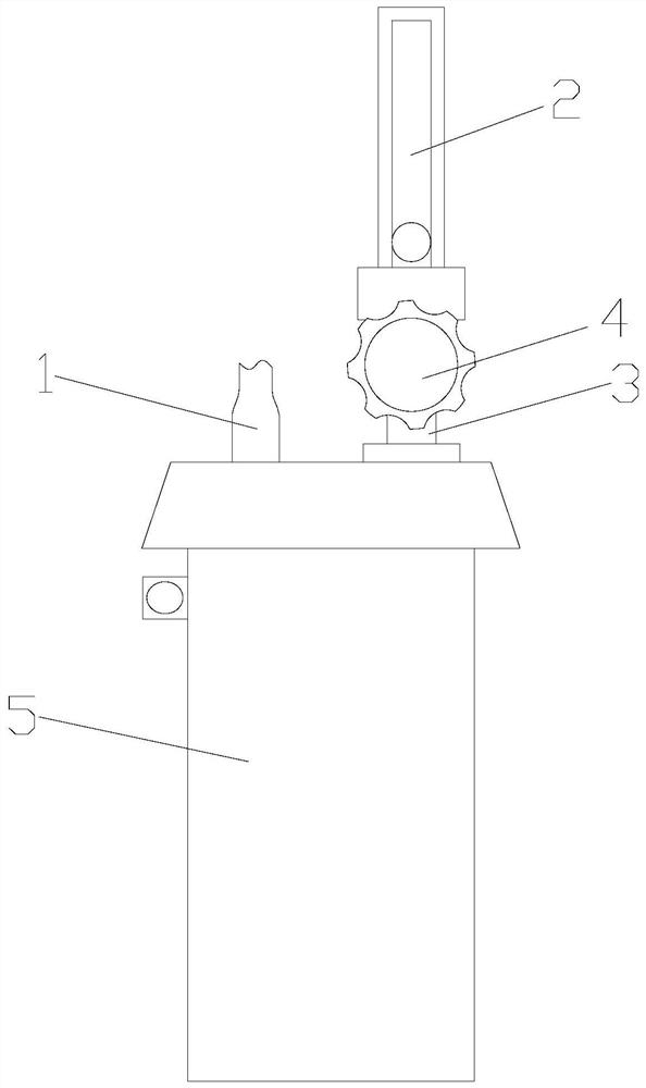
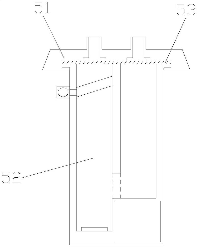
[0030] see Figure 1-Figure 5, the present invention provides an oxygen delivery device for obstetrics and gynecology. The humidification bottle 5 has a cylindrical structure and is placed vertically. The oxygen inhalation connecting pipe 1 is nested on the left end of the upper surface of the silent humidification bottle 5. The oxygen supply connecting pipe 3 is located on the right side of the upper surface of the silent humidification bottle 5 and is connected to the The oxygen inhalation connecting pipes 1 are parallel to each other, the flow meter 2 is above the oxygen supply connecting pipe 3, and the flow regulating valve 4 is nested at the connection between the flow meter 2 and the oxygen supply connecting pipe 3; the silent humidification bottle 5 is composed of Sealing bottle cap 51, ultrasonic humidification bottle 52, sealing rubber pad 53, the ultrasonic humidification bottle 52 is a hollow cylindrical structure without a top, the sealing bottle cap 51 is fastene...
Embodiment 2
[0033] see Figure 6-Figure 8 The humidity controller 529 is composed of a liquefaction baffle a1, an adjustment handle a2, a driving block a3, and a fixed shaft a4. The fixed shaft a4 is nested in the middle of the baffle 526. On the left side surface of the gas pipe 522, the drive block a3 is fastened to the right side of the adjustment handle a2, and is in sliding fit with the left end of the inner wall of the humidification exhaust pipe 522. One end of the liquefaction baffle a1 is fastened to the drive block a3, and the other One end and the fixed shaft a4 adopt clearance fit. The liquefaction baffle a1 is composed of a fixed pipe a11, a reset shaft a12, a main body of the baffle a13, and a traction block a14. The reset shaft a12 is nested in the middle of the fixed tube a11, the traction block a14 is fastened with the surface of the driving block a3 facing the fixed shaft a4, one end of the baffle main body a13 is wound and connected with the reset shaft a12, and the ot...
PUM
 Abstract
Description
Claims
Application Information
 - R&D
- Intellectual Property
- Life Sciences
- Materials
- Tech Scout
- Unparalleled Data Quality
- Higher Quality Content
- 60% Fewer Hallucinations
Browse by: Latest US Patents, China's latest patents, Technical Efficacy Thesaurus, Application Domain, Technology Topic, Popular Technical Reports.
© 2025 PatSnap. All rights reserved.Legal|Privacy policy|Modern Slavery Act Transparency Statement|Sitemap|About US| Contact US: help@patsnap.com


