Substrate drying chamber

A technology for drying chambers and substrates, applied in electrical components, semiconductor/solid-state device manufacturing, circuits, etc., and can solve problems such as particle pollution

Pending Publication Date: 2020-12-22
MUJIN ELECTRONICS CO LTD
View PDF1 Cites 0 Cited by
  • Summary
  • Abstract
  • Description
  • Claims
  • Application Information

AI Technical Summary

Problems solved by technology

[0020] The technical purpose of the present invention is to solve the following problems: in the process of storing supercritical fluid with high pressure in a supercritical fluid generator arranged outside the drying chamber, and then introducing it into the drying chamber through pipelines and valves (initial charging) pressure), due to the cooling phenomenon caused by the pressure drop at the connection part of the pipe and the valve, the supercritical fluid is liquefied or vaporized to cause particulate contamination on the substrate

Method used


Image

  • Substrate drying chamber
  • Substrate drying chamber
  • Substrate drying chamber

Examples


Embodiment Construction

[0051] Since the specific structural or functional descriptions of the embodiments according to the inventive concepts disclosed herein are only exemplary for describing the embodiments according to the inventive concepts, the embodiments according to the inventive concepts may be embodied in various forms, But not limited to the embodiments described herein.

[0052] While the embodiments of the invention are susceptible to various modifications and alternative forms, specific embodiments thereof are shown by way of example in the drawings and herein will be described in detail. It should be understood, however, that there is no intention to limit the invention to the particular forms disclosed, but on the contrary, the invention is to cover all modifications, equivalents, and alternatives falling within the spirit and scope of the invention.

[0053] It will be understood that, although the terms "first", "second", etc. may be used herein to describe various elements, these ...


PUM


Abstract

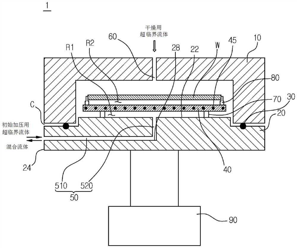
A substrate drying chamber includes: a substrate placement plate; an upper supply port that provides a supply path for the supercritical fluid for drying; an integrated supply and discharge port thatprovides a supply path for the supercritical fluid for initial pressurization and a discharge path for a mixed fluid in which an organic solvent is dissolved in the supercritical fluid for drying after drying is performed; and a heating member that heats the supercritical fluid for initial pressurization and the mixed fluid. According to the present invention, it is possible to solve the problem of causing particulate contamination on a substrate by liquefying or vaporizing a supercritical fluid due to a cooling phenomenon caused by a decrease in pressure in a process of introducing the supercritical fluid for initial pressurization into a chamber; the problem addressed by the present invention is that of causing microparticle contamination on a substrate or collapsing a pattern formed onthe substrate due to the surface tension of a mixed fluid by phase separation of the mixed fluid due to a cooling effect when the mixed fluid is discharged after the completion of a drying step.

Description

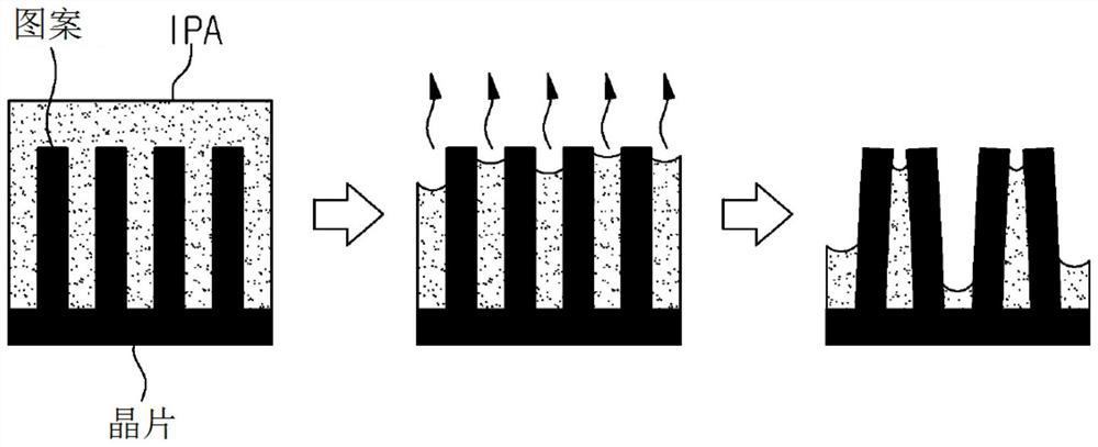
technical field [0001] The invention relates to a substrate drying chamber. More specifically, the present invention relates to a substrate drying chamber in which the problem that can be solved is that due to the The cooling phenomenon caused by the pressure drop causes the supercritical fluid to be liquefied or vaporized to cause particle contamination on the substrate; the problem that can be solved is that when the mixed fluid of isopropanol (IPA) is dissolved in the supercritical fluid When discharging (depressurization), the mixed fluid phase separates due to cooling, thereby causing particle contamination on the substrate, or the pattern formed on the substrate is collapsed due to the surface tension of the mixed fluid; Symmetric flow is guided during discharge to uniformly disperse the supercritical fluid into the chamber for supply and discharge to improve substrate drying efficiency; and when the chamber is opened after completing the drying process, particles can b...

Claims


Application Information

Patent Timeline
IPC IPC(8): H01L21/67
CPCH01L21/67034H01L21/67017H01L21/67098H01L21/683H01L21/67248H01L21/6715H01L21/67126H01L21/67259
Inventor 申熙镛李泰京尹炳文
Owner MUJIN ELECTRONICS CO LTD
Why Eureka
Try Eureka