
Numerical prediction method for two-phase flow and phase change process in gas-containing hydraulic turbine

A numerical prediction and phase flow technology, applied in CAD numerical modeling, electrical digital data processing, instruments, etc., can solve problems such as difficult prediction, difficulty in describing the fine structure of phase interface, and description distortion

Pending Publication Date: 2020-12-22
ZHEJIANG SCI-TECH UNIV
View PDF0 Cites 2 Cited by
  • Summary
  • Abstract
  • Description
  • Claims
  • Application Information

AI Technical Summary

Problems solved by technology

[0004] At present, most of the simulation methods for two-phase flow processes use averaged mathematical models, and the averaged process will lead to distortion of the description of their objective phenomena, and the traditional multiphase flow model also has great difficulties in predicting the flow process. : The method based on volume average can only describe the distribution of gas phase content macroscopically, and the interface capture method is also difficult to describe the fine structure of the phase interface

Method used


Image

  • Numerical prediction method for two-phase flow and phase change process in gas-containing hydraulic turbine
  • Numerical prediction method for two-phase flow and phase change process in gas-containing hydraulic turbine
  • Numerical prediction method for two-phase flow and phase change process in gas-containing hydraulic turbine

Examples


Embodiment Construction

[0055] The present invention will be further described below in conjunction with the accompanying drawings.

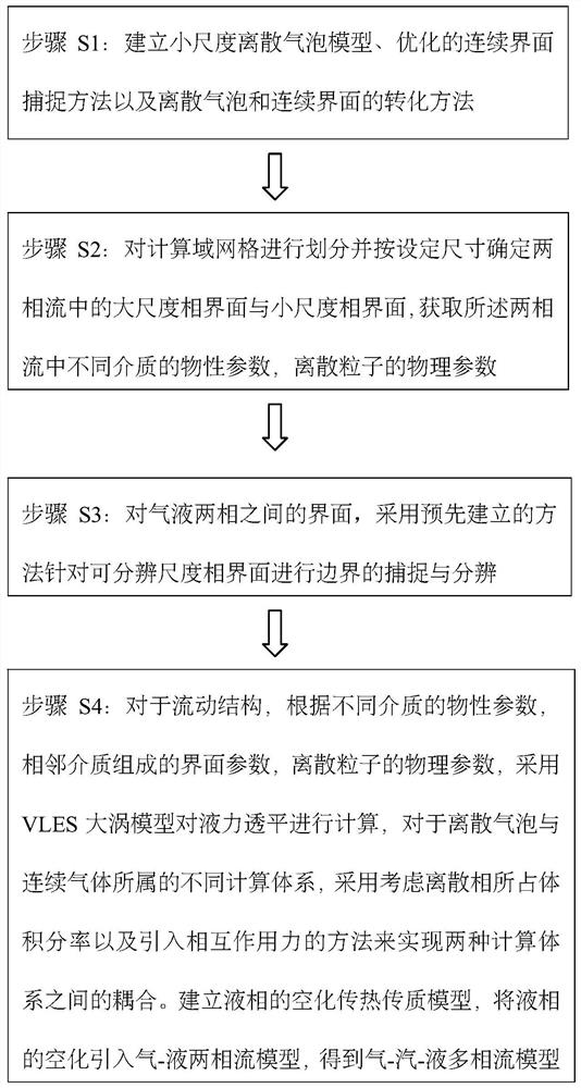
[0056] Such as figure 1 A numerical prediction method for two-phase flow and phase change process in a gas-containing hydraulic turbine is shown, including the following steps: Step S1: Establish a small-scale discrete bubble model, an optimized continuous interface capture method, and the conversion of discrete bubbles and continuous interfaces method;

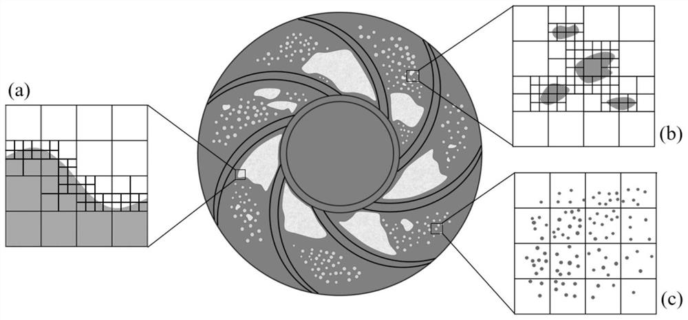
[0057] Step S2: Divide the calculation domain grid and determine the large-scale phase interface and small-scale phase interface in the two-phase flow according to the set size, and obtain the physical parameters of different media in the two-phase flow and the physical parameters of discrete particles; The scale is that the size of the phase interface is greater than or equal to the grid size of the calculation domain, and the small scale is that the size of the phase interface is smaller than the grid size of the c...


PUM


Abstract

The invention relates to a two-phase flow numerical prediction technology. According to the technical scheme, a numerical prediction method for a two-phase flow and the phase change process in a gas-containing hydraulic turbine comprises the following steps of S1, establishing a small-scale discrete bubble model, an optimized continuous interface capture method and a discrete bubble and continuousinterface conversion method; S2, dividing a computational domain grid, determining a large-scale phase interface and a small-scale phase interface in the two-phase flow according to a set size, and obtaining physical property parameters of different media in the two-phase flow and physical parameters of discrete particles; s3, for the interface between the gas phase and the liquid phase, capturing and distinguishing the boundary of the distinguishable scale phase interface by adopting the method established in the step S1; and S4, establishing a cavitation heat and mass transfer model of theliquid phase, and introducing cavitation of the liquid phase into the gas-liquid two-phase flow model to obtain a gas-steam-liquid multi-phase flow model. The method can be used for analyzing the gas-liquid two-phase flow and cavitation combined transient flow in the gas-containing hydraulic turbine.

Description

technical field [0001] The two-phase flow numerical prediction technology involved in the present invention, in particular, relates to a numerical prediction method for two-phase flow and phase change process in a gas-containing hydraulic turbine. Background technique [0002] The use of hydraulic turbines to recover fluid energy in large-scale process industries such as petrochemical, seawater desalination, and iron and steel metallurgy is of great significance to the energy saving of process industry systems. The structural type of hydraulic turbines is mainly reverse centrifugal pumps. With the increasing complexity of the transmission medium and operating conditions in the process industry, the working medium of the hydraulic turbine develops from a pure liquid phase to an easily vaporized and gas-liquid two-phase mixed medium. At this time, the complex flow channel structure and The rapid change of the inlet and outlet pressure will lead to the cavitation of the easily ...

Claims


Application Information

Patent Timeline
Patent Type & Authority Applications(China)
IPC IPC(8): G06F30/28G06F111/10G06F113/08G06F119/14
CPCG06F30/28G06F2111/10G06F2113/08G06F2119/14
Inventor 李林敏薛键杨徽李晓俊朱祖超
Owner ZHEJIANG SCI-TECH UNIV
Learn More