
Double-motor-driven extruder

A dual-motor drive and extruder technology, which is applied in the field of polymer material processing equipment, can solve the problems that the rotation direction of the two screws cannot be changed again at any time, it is difficult to achieve ultra-high speed, and it is impossible to achieve large filling, etc., to achieve stable rotation , prevent the barrel from rotating, and improve the effect of the speed limit

Inactive Publication Date: 2020-12-22
WUYI UNIV
View PDF6 Cites 2 Cited by
  • Summary
  • Abstract
  • Description
  • Claims
  • Application Information

AI Technical Summary

Problems solved by technology

Existing extruders, whether single-screw extruders or twin-screw extruders, are driven by a single motor at the feed end of the extruder, and it is difficult to achieve ultra-high speed
[0003] Existing extruders are driven by a single motor. Although the function of different speed ratios of the two screws can be achieved through belt transmission, gear transmission or other combinations, the speed ratio has been fixed at the time of design, and the speed cannot be adjusted later. Compare
Adjusting the speed ratio through the gear box can only achieve the same or different rotation mode, and the rotation direction of the two screws cannot be changed again at any time
When the twin-screw scheme is adopted, the support of the screw barrel is supported by a cantilever, which is very unstable after the speed is increased, and the tail "sweeping" phenomenon occurs, making it difficult to achieve ultra-high speed
The feeding method adopts the gravity feeding method, which cannot achieve large filling, and the conveying capacity is also insufficient. Moreover, how to maintain good sealing performance is also a technical problem when realizing high-speed operation.
Existing camera devices for extruders cannot quickly change the number of cameras as needed when directly observing the shape changes of materials during extrusion

Method used


Image

  • Double-motor-driven extruder
  • Double-motor-driven extruder
  • Double-motor-driven extruder

Examples


Embodiment Construction

[0042] This part will describe the specific embodiment of the present invention in detail, and the preferred embodiment of the present invention is shown in the accompanying drawings. Each technical feature and overall technical solution of the invention, but it should not be understood as a limitation on the protection scope of the present invention.

[0043] In the description of the present invention, it should be understood that the orientation descriptions, such as up, down, front, back, left, right, etc. indicated orientations or positional relationships are based on the orientations or positional relationships shown in the drawings, and are only In order to facilitate the description of the present invention and simplify the description, it does not indicate or imply that the device or element referred to must have a specific orientation, be constructed and operated in a specific orientation, and thus should not be construed as limiting the present invention.

[0044] I...


PUM


Abstract

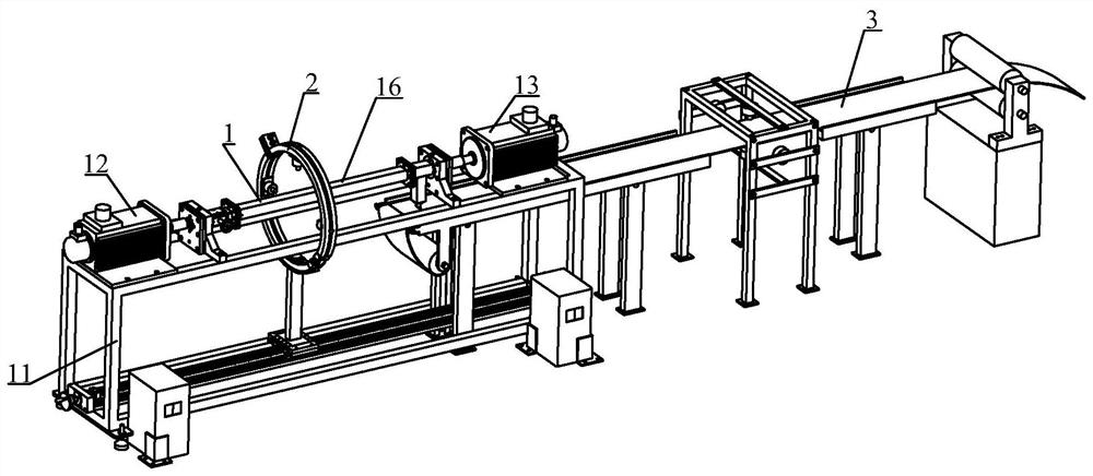
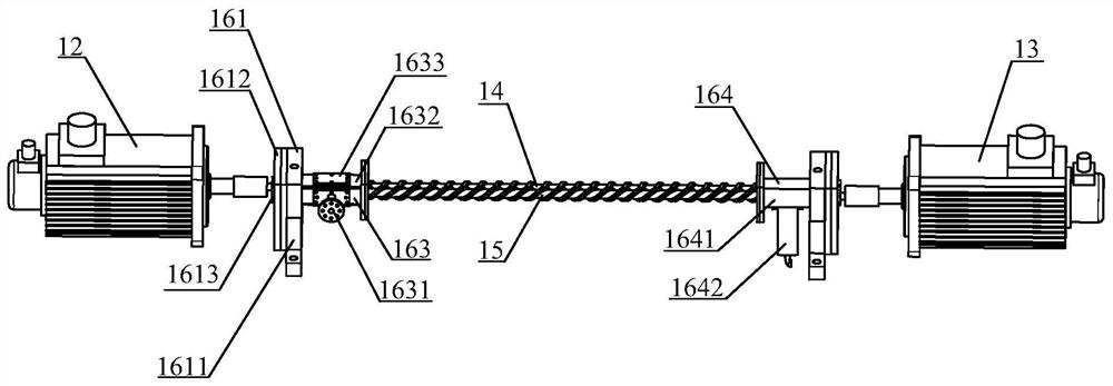
The invention relates to the field of high polymer material processing equipment, in particular to a double-motor-driven extruder. The extruder comprises an extrusion device, wherein the extrusion device comprises a rack, a first motor, a second motor, a first screw, a second screw and a machine barrel mechanism, the machine barrel mechanism is fixedly arranged on the rack, the first screw and thesecond screw are rotatably arranged in a cavity of the machine barrel mechanism, the two ends of the first screw and the two ends of the second screw extend out of the cavity, the first motor and thesecond motor are arranged face to face and fixed to the two ends of the machine barrel mechanism respectively, one end of the first screw is fixedly connected with the first motor, one end of the second screw is fixedly connected with the second motor, the first screw is provided with a first left-hand thread structure, the second screw is provided with a second left-hand thread structure, and the first left-hand thread structure abuts against the second left-hand thread structure; and the first motor and the second motor are driven through control signals, and then the first screw and the second screw are driven to rotate in the machine barrel structure. The rotating speed ratio and the rotating direction of the extruder can be adjusted randomly, and the sealing effect is good.

Description

technical field [0001] The invention relates to the field of polymer material processing equipment, in particular to a dual-motor driven extruder. Background technique [0002] The twin-screw extruder is developed on the basis of the single-screw extruder. Due to its good feeding performance, mixing and plasticizing performance, exhaust performance, and extrusion stability, it has been widely used in extruded products. molding processing. Existing extruders, no matter single-screw extruders or twin-screw extruders, are all driven by a single motor at the feed end of the extruder, so it is difficult to achieve ultra-high speed. [0003] Existing extruders are driven by a single motor. Although the function of different speed ratios of the two screws can be achieved through belt transmission, gear transmission or other combinations, the speed ratio has been fixed at the time of design, and the speed cannot be adjusted later. Compare. Adjusting the speed ratio through the ge...

Claims


Application Information

Patent Timeline
Patent Type & Authority Applications(China)
IPC IPC(8): B29C48/25B29C48/265B29C48/40B29C48/92
CPCB29C48/252B29C48/254B29C48/402B29C48/265B29C48/92
Inventor 张志旋徐百平喻慧文肖书平梁勇曹明轩
Owner WUYI UNIV
Learn More