Eureka AIR delivers breakthrough ideas for toughest innovation challenges, trusted by R&D personnel around the world.

Automobile brake drum pouring device

A technology for automobile brakes and casting molds, which is applied in the manufacture of tools, heat exchangers, lighting and heating equipment, etc. It can solve the problems of long cooling time, reduced processing efficiency, and unsatisfactory results, so as to save resources and improve production Efficiency, the effect of improving the cooling effect

Inactive Publication Date: 2020-12-22
十堰市宏昌达工贸股份有限公司
View PDF0 Cites 2 Cited by
  • Summary
  • Abstract
  • Description
  • Claims
  • Application Information

AI Technical Summary

Problems solved by technology

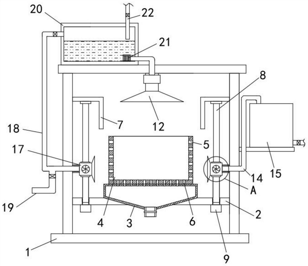
[0004] The purpose of the present invention is to solve the problem in the prior art that there is no cooling mechanism on the pouring device, the brake drum needs to be soaked in the cooling pool after pouring, the cooling time is long, the effect is not very ideal, and the processing efficiency is reduced. Automobile brake drum pouring device

Method used


Image

  • Automobile brake drum pouring device
  • Automobile brake drum pouring device
  • Automobile brake drum pouring device

Examples


Embodiment Construction

[0019] The following will clearly and completely describe the technical solutions in the embodiments of the present invention with reference to the accompanying drawings in the embodiments of the present invention. Obviously, the described embodiments are only some, not all, embodiments of the present invention.

[0020] In describing the present invention, it should be understood that the terms "upper", "lower", "front", "rear", "left", "right", "top", "bottom", "inner", " The orientation or positional relationship indicated by "outside", etc. is based on the orientation or positional relationship shown in the drawings, and is only for the convenience of describing the present invention and simplifying the description, rather than indicating or implying that the referred device or element must have a specific orientation, so as to Specific orientation configurations and operations, therefore, are not to be construed as limitations on the invention.

[0021] refer to Figure ...


PUM


Abstract

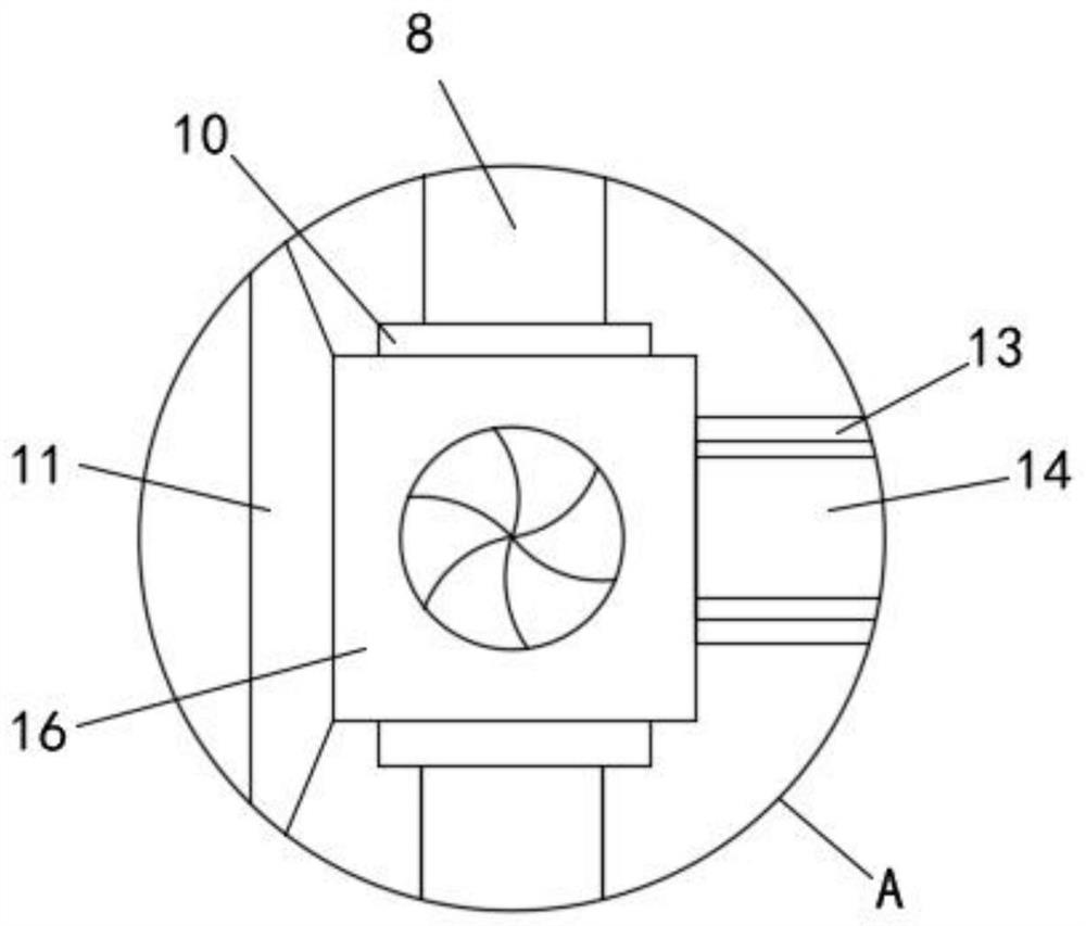
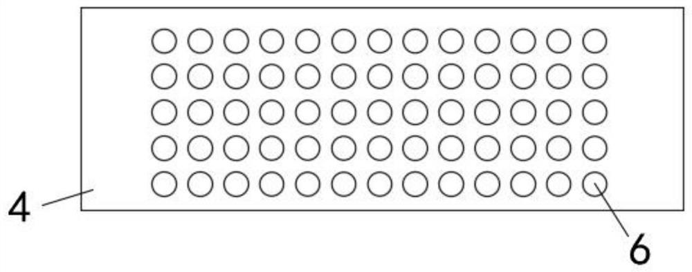
The invention discloses an automobile brake drum pouring device. The automobile brake drum pouring device comprises a supporting frame; transverse plates are fixed to the lower parts of the two sidesof the inner wall of the supporting frame; a recycling box is mounted on the transverse plates; a pouring mold shell is assembled at the top of the recycling box; a plurality of air holes are formed in the side walls of the two sides of the pouring mold shell; a plurality of water outlet holes are formed in the bottom of the pouring mold shell and the top of the recycling box correspondingly; an air heater and an air cooler are arranged on the two sides of the pouring mold shell correspondingly; and reciprocating mechanisms are connected to the air heater and the air cooler correspondingly; awater tank is fixed to one side of the top of the supporting frame; a water pump is assembled on the inner bottom wall of the water tank; a spraying cover is connected to the water outlet end of the water pump; the spraying cover is located right above the pouring mold shell; and cold air pipes are fixed to the upper part of one side of the inner wall of the water tank and the air inlet end of theair cooler. According to the automobile brake drum pouring device, uniform heat absorption and heat dissipation of the pouring mold shell are achieved, the cooling effect is improved, the product quality is guaranteed through all-around uniform cooling, the design is reasonable, the practicability is high, and the automobile brake drum pouring device is suitable for popularization.

Description

technical field [0001] The invention relates to the technical field of pouring devices for brake drums, in particular to a pouring device for brake drums of automobiles. Background technique [0002] The brake drum is the friction couple of the drum brake. In addition to the strength and rigidity required as a component, it should also have as high and stable a friction coefficient as possible, as well as appropriate wear resistance, heat resistance, and heat dissipation. and heat capacity etc. [0003] During the processing of the brake drum, liquid metal enters the brake drum forming mold. At present, the brake drum is generally formed by continuous casting. It is necessary to quickly cool the brake drum that has just been processed, so that the brake drum can be cast Take it out of the mold, there is no cooling mechanism on the existing pouring device, the brake drum needs to be soaked in the cooling pool after pouring, the cooling time is long, the effect is not very sa...

Claims


Application Information

Patent Timeline
IPC IPC(8): B22C9/22B22D27/04B22C9/06F28D21/00
CPCB22C9/065B22C9/22B22D27/04F28D21/0001
Inventor 胡玉梅胡军
Owner 十堰市宏昌达工贸股份有限公司
Why Eureka
Eureka Blog
Learn More