Eureka AIR delivers breakthrough ideas for toughest innovation challenges, trusted by R&D personnel around the world.

Single-photon avalanche photodiode calibration system and calibration method

A photodiode and single-photon avalanche technology, applied in the field of quantum communication, can solve the problems of high efficiency and convenience without SPAD tubes, calibration systems and methods, etc., and achieve the effect of easy learning, simple operation, and lower professional level of testers

Pending Publication Date: 2020-12-18
QUANTUMCTEK
View PDF1 Cites 5 Cited by
  • Summary
  • Abstract
  • Description
  • Claims
  • Application Information

AI Technical Summary

Problems solved by technology

However, the above-mentioned patent application is for the test of single photon detectors, and there is no efficient and convenient calibration system and method for SPAD tubes at present.

Method used


Image

  • Single-photon avalanche photodiode calibration system and calibration method
  • Single-photon avalanche photodiode calibration system and calibration method
  • Single-photon avalanche photodiode calibration system and calibration method

Examples


Embodiment 1

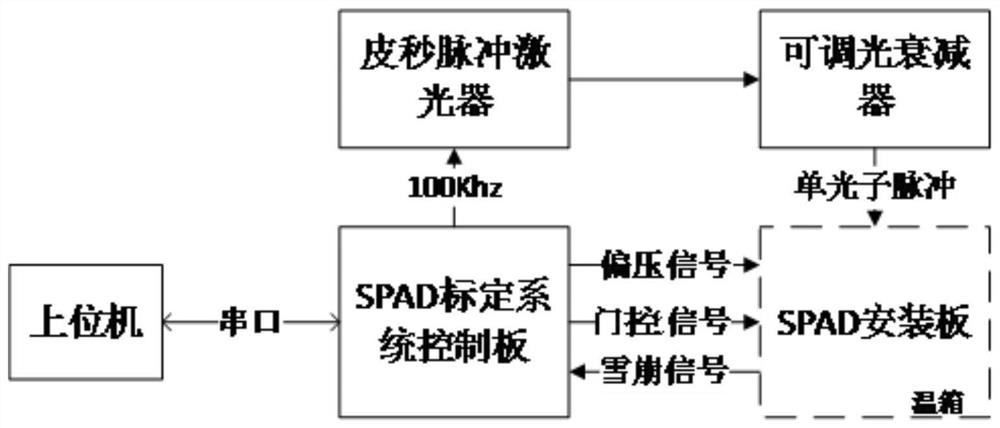
[0069] Such as figure 1 As shown, a single photon avalanche photodiode calibration system includes: host computer, SPAD calibration system control board, picosecond pulse laser, adjustable optical attenuator, SPAD installation board, and temperature box.

[0070] The SPAD calibration system control board is connected to the picosecond pulse laser through an SMA connection line, and the SPAD calibration system control board generates a light source driving signal and sends it to the picosecond pulse laser.

[0071] The picosecond pulse laser as a calibration light source is connected to the adjustable optical attenuator through an optical fiber, and the picosecond pulse laser outputs light pulses to the adjustable optical attenuator.

[0072] The adjustable optical attenuator is connected to the SPAD to be tested through an optical fiber, and the adjustable optical attenuator attenuates the received optical pulse, and outputs a single-photon level pulsed optical signal to the S...

Embodiment 2

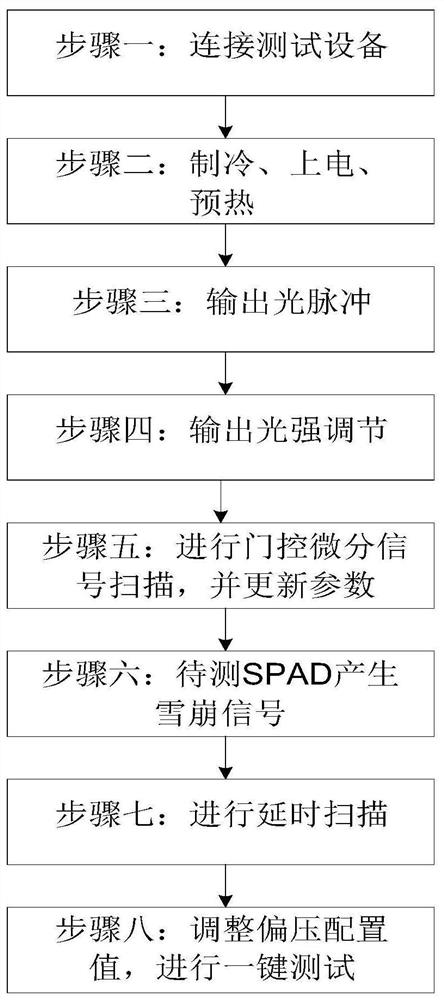
[0088] Such as image 3 As shown, the present invention discloses a single photon avalanche photodiode calibration method based on the calibration system described in Embodiment 1, comprising the following steps:

[0089] Step 1: Connect test equipment;

[0090] Step 2: Refrigeration, power on, and preheating;

[0091] Step 3: output light pulse;

[0092] Step 4: Output light intensity adjustment;

[0093] Step 5: Carry out gated differential signal scanning;

[0094] Step 6: The SPAD to be tested generates an avalanche signal;

[0095] Step 7: Perform delayed scanning;

[0096] Step 8: Adjust the bias voltage configuration value and perform a one-key test.

[0097] Described step one is specifically:

[0098] (1) Establish the data connection between the host computer and the SPAD calibration system control board;

[0099] (2) Establish the hardware connection between the control board of the SPAD calibration system, the picosecond pulse laser, the adjustable optical ...


PUM


Abstract

The invention discloses a single-photon avalanche photodiode calibration system, relates to the field of quantum communication, and solves the problem of how to accurately and automatically test SPADkey parameters. The system comprises an upper computer, an SPAD calibration system control panel, a picosecond pulse laser, a variable optical attenuator, an SPAD mounting plate and a temperature box;the SPAD calibration system control panel is connected with the picosecond pulse laser; the picosecond pulse laser is connected with the variable optical attenuator; the variable optical attenuator is connected to an SPAD to be tested through an optical fiber, and the mounting plate is provided with a gating signal interface, a bias signal interface and an avalanche signal interface. The SPAD tobe tested is mounted on the mounting plate; the mounting plate is mounted in the temperature box; the calibration system control panel is connected with the upper computer; the invention further provides a single-photon avalanche photodiode calibration method. The system has the advantages that multiple performance parameters of the SPAD to be tested can be tested in a short time, and the system is efficient, convenient, easy to operate and easy to learn.

Description

technical field [0001] The invention relates to the field of quantum communication, in particular to a single photon avalanche photodiode calibration system and a calibration method. Background technique [0002] Single Photon Avalanche Diode (SPAD) is a key common device in the field of quantum communication. The development of quantum communication to higher speed and longer distance directly depends on the continuous progress of this core technology. The performance of SPAD is determined comprehensively by key parameters such as detection efficiency, dark count rate, and afterpulse, and these key parameters often affect and restrict each other. Therefore, the measurement of key parameters of SPAD is a systematic work. Only by comprehensively measuring the related parameters can the real performance of SPAD be reflected. At the same time, studying the optimal operating voltage and dark current of single photon avalanche photodiodes is of great significance for improving t...

Claims


Application Information

Patent Timeline
IPC IPC(8): G01R31/26G01J11/00
CPCG01J11/00G01R31/2601G01R31/2635
Inventor 蒋连军马睿唐世彪王泉刘酩
Owner QUANTUMCTEK
Why Eureka
Eureka Blog
Learn More