Multifunctional video parameter calibration device

A technology for video parameters and calibration devices, applied in television, electrical components, image communication, etc., can solve problems such as chrominance-brightness gain difference and time delay difference, cumbersome programming and signal processing, brightness nonlinear distortion, etc. Professional level requirements, easy to use, good real-time effects

Active Publication Date: 2021-04-23
BEIJING TIRT TECH SERVICE
View PDF5 Cites 4 Cited by
  • Summary
  • Abstract
  • Description
  • Claims
  • Application Information

AI Technical Summary

Problems solved by technology

The calibration system is complicated to build and the test efficiency is low. Among them, the phase shifter, phase meter, subcarrier signal generator and programmable video signal generator have all been discontinued, and after-sales service and technical support are no longer provided
[0004] In addition, since the original measurement system is performing differential gain and differential phase distortion, luminance nonlinear distortion, chroma-luminance gain difference and delay difference, K coefficient, multi-burst group, SINX / X frequency response and group delay, The calibration of field time waveform distortion and line time waveform distortion items requires cumbersome programming and signal processing to achieve, and requires high professional level of measurement personnel, which is not conducive to the use and popularization of testing and measuring instruments
Therefore, the original test system can no longer meet the calibration requirements of the current vector oscilloscope, waveform monitor and video analyzer, so a set of advanced technology, easy to use and maintain video parameter calibration device is needed to meet the calibration of video measuring instruments need

Method used


Image

  • Multifunctional video parameter calibration device
  • Multifunctional video parameter calibration device
  • Multifunctional video parameter calibration device

Examples


Embodiment Construction

[0079] The multifunctional video parameter calibration device in the present invention will be further described below in conjunction with specific embodiments and accompanying drawings. In addition, the embodiments of the present invention are not limited to the embodiments and modifications described below, and can also be implemented without departing from Various changes, substitutions, and deformations are possible within the scope of the technical idea of ​​the present invention. Furthermore, if the technical idea of ​​the present invention is realized by other methods due to technical progress or other derived technologies, this method can also be used for implementation. Therefore, the appended claims cover all the embodiments that can be included within the scope of the technical idea of ​​the present invention.

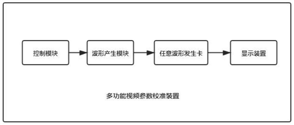
[0080] Such as figure 1 As shown, the present invention provides a multifunctional video parameter calibration device, comprising: a control module, a wave...


PUM


Abstract

The invention relates to a multifunctional video parameter calibration device, and the device comprises a control module, a waveform generation module, an arbitrary waveform generation card and a display device; the control module is used for receiving parameters input by a user and sending the parameters to the waveform generation module; the waveform generation module is used for generating waveform data of test signals according to parameters input by a user and sending the waveform data to the arbitrary waveform generation card, and the test signals comprise a video test signal, a test signal for waveform monitor calibration, a test signal for vector oscilloscope calibration and a test signal for video analyzer calibration; the arbitrary waveform generation card is used for outputting test signals and is provided with a plurality of signal output channels so as to simultaneously generate multiple paths of test signals; and the display device is used for displaying the waveform of the test signal output by the waveform generation card. The device can replace various instruments and equipment, calibrate various video measuring instruments and realize chroma phase traceability, has strong pertinence, and is convenient and rapid to test.

Description

technical field [0001] The invention relates to the technical field of calibration of video measuring instruments, in particular to a multifunctional video parameter calibration device. Background technique [0002] Waveform monitors, vector oscilloscopes, and video analyzers are special instruments for color TV signal measurement and analysis. They are widely used in laboratories and TV manufacturers and are important measuring instruments in the video field. Luminance level, chroma level and chroma phase are the basic parameters of video measurement, and their measurement calibration and traceability are the key points in video measurement, but their traceability is relatively difficult at present, especially the traceability of chroma phase. [0003] At present, the calibration specifications of waveform monitors, vector oscilloscopes and video analyzers in my country are "JJFXXXX-2020 Calibration Specifications for Waveform Monitors", "JJF1387-2013 Calibration Specificat...

Claims


Application Information

Patent Timeline
Patent Type & Authority Applications(China)
IPC IPC(8): H04N17/02
CPCH04N17/02
Inventor 刘雷刘志刚韩正涛陈鹏韩东闫实蒋治国李亚芳
Owner BEIJING TIRT TECH SERVICE
Why Eureka
Try Eureka