Tactile sensors

A tactile sensor and sensor technology, applied in the field of tactile sensors, can solve the problems of high cost, tactile sensors without industrial robots, and huge size

Pending Publication Date: 2020-12-18
THE HONG KONG UNIV OF SCI & TECH
View PDF0 Cites 1 Cited by
  • Summary
  • Abstract
  • Description
  • Claims
  • Application Information

AI Technical Summary

Problems solved by technology

However, vision-based tactile sensors have not been applied to state-of-the-art industrial robots due to relatively bulky size, high cost, and repeatability issues.

Method used


Image

  • Tactile sensors
  • Tactile sensors
  • Tactile sensors

Examples


Embodiment Construction

[0040] The present invention will be described below through detailed description of the embodiments.

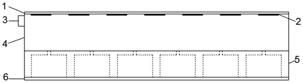
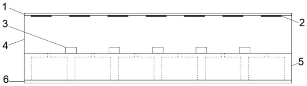
[0041] exist Figure 1A, a schematic diagram of a pinhole array-based tactile sensor is shown. The device comprises a reflective layer 1 for illumination reflection, an elastomeric layer 4 on top of which is a marker 2, one or a series of LEDs 3 to provide illumination for imaging, a pinhole-based lens structure 5 and a CMOS (complementary metal oxide Semiconductor) sensor 6. One or a series of LEDs 3 will provide illumination to the elastomeric body 4 and they are located on the side(s) of the elastomeric body 4 .

[0042] In this embodiment, the reflective layer 1 is a flexible layer with high light reflectivity, and its shape can be changed according to external touch. The material of the reflective layer 1 can be silicone resin, parylene C, polyimide and other polymers, and other inorganic materials, as long as it can be deformed by combining with the underlying elasti...


PUM

PropertyMeasurementUnit
thicknessaaaaaaaaaa

Abstract

The present disclosure provides a sensing device, a tactile sensing device, and a tactile sensor. The sensing device includes: a photosensitive sensor; a pinhole array structure located on the photosensitive sensor; an elastomer layer positioned on one side, far away from the photosensitive sensor, of the pinhole array structure; a reflecting layer positioned on one side, far away from the pinholearray structure, of the elastomer layer; and a light source located between the reflective layer and the pinhole array structure.

Description

technical field [0001] The present disclosure relates to vision-based tactile sensors, especially for sensing three-dimensional surface deformation and force distribution in contact areas. Background technique [0002] Tactile sensors are currently used in many fields, such as robotics and medical surgery. For example, for a grip-operated system, tactile sensors are necessary to generate effective feedback to maintain a stable grip during movement. [0003] Various types of tactile sensors with different conversion methods, including capacitive, piezoelectric, and piezoresistive, have been widely developed in recent decades. They cover a wide range from micro to macro and have a wide range of applications. However, they lack the capability of high-resolution spatial mapping and three-dimensional measurement due to their high complexity in terms of mechanical structure, readout circuit design, and interface. [0004] Vision-based tactile sensors are flourishing in various ...

Claims


Application Information

Patent Timeline
Patent Type & Authority Applications(China)
IPC IPC(8): G01B11/24G01B11/02G01L1/25
CPCG01B11/24G01B11/02G01L1/25G01L1/247G01L1/241G01L5/166G01L1/242B25J13/084
Inventor 于宏宇王煜陈侠张雅展
Owner THE HONG KONG UNIV OF SCI & TECH
Why Eureka
Try Eureka