
High-speed load increasing peak regulation system and method of thermal power generating unit

A thermal power unit and load-raising technology, applied in the direction of separation methods, chemical instruments and methods, mechanical equipment, etc., can solve problems such as lack of capacity, unsustainable primary frequency regulation ability, weak peak-shaving ability of rising load, etc., to achieve response speed and reliability Good, the effect of improving the ability to deal with large low-frequency disturbances

Pending Publication Date: 2020-12-18
XIAN THERMAL POWER RES INST CO LTD
View PDF0 Cites 1 Cited by
  • Summary
  • Abstract
  • Description
  • Claims
  • Application Information

AI Technical Summary

Problems solved by technology

[0013] Based on the above analysis, it can be found that the high-speed primary frequency regulation cannot last long, and the large and long-lasting AGC and tertiary frequency regulation cannot achieve high-speed peak regulation, and in high-load conditions such as peak power consumption in summer, a large number of units operate at rated load. The ability to increase load peak regulation is very weak, which is also the biggest problem facing the load dispatching of the receiving power grid at present, that is, there is a lack of a high-speed and large-scale load regulation method to deal with large load disturbances

Method used


Image

  • High-speed load increasing peak regulation system and method of thermal power generating unit

Examples


Embodiment Construction

[0029] The present invention will be described in further detail below in conjunction with the accompanying drawings and specific embodiments.

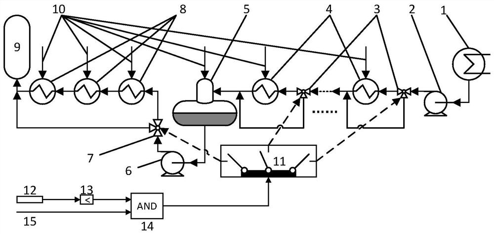
[0030] Conventional thermal power unit heat recovery system as attached figure 1As shown, the condensed water from the condenser 1 is sent into the condensed water system pipeline by the condensed water pump 2, flows through multiple (mostly 4) low-pressure heaters 4 and its low-pressure bypass valve 3, and is fed by the steam turbine After steam turbine extraction 10 is heated, it flows into the deaerator 5, and in the deaerator 5, the high-temperature steam turbine extraction 10 is used for deaeration, and then is pumped into the water supply system pipeline by the feed water pump 6, and flows through multiple (usually 3) ) high-pressure heater 8 and its high-pressure bypass valve 7, and finally enter the boiler 9.

[0031] Multiple low-load bypass valves 3 and high-load bypass valves 7 are all three-way switching valves. When the...


PUM


Abstract

The invention discloses a high-speed load increasing peak regulation system and method of a thermal power generating unit. According to the high-speed load increasing peak regulation system and methodof the thermal power generating unit, a high-precision power grid side frequency meter is adopted to measure power grid frequency of a main transformer high-voltage side, the power grid frequency isinput to a lower limit-crossing trigger module, when the power grid frequency is lower than a frequency action lower limit set by the lower limit-crossing trigger module, a high-speed load increasingdemand signal is output and sent to a load increasing peak regulation action and gate, when the high-speed load increasing demand signal and the high-speed load increasing permission instruction fromthe thermal power generating unit are simultaneously ture or 1, a final high-speed load increasing action instruction is output, entering a high-speed load increasing peak regulation control action selection switch group is carried out , a corresponding bypass valve is switched according to the switch configuration of the action group capable of being reselected, and high-speed load increasing peak regulation of the thermal power generating unit is realized. According to the high-speed load increasing peak regulation system and method of the thermal power generating unit, remote triggering ofpower grid dispatching is not needed, the response speed and reliability are good, the system is used for power grid dispatching in emergency, and the system particularly has important practical significance for the power grid of the middle-east receiving end area where ultra-high-voltage high-power long-distance power transmission is implemented in China.

Description

technical field [0001] The invention relates to the technical field of automatic control of thermal power plants, in particular to a system and method for peak load regulation by limit-up load of a thermal power unit. Background technique [0002] my country's three northern regions are rich in wind and light resources. In recent years, the installed capacity of wind power and photovoltaics has continued to grow rapidly. These local grids that receive high-power transmission are called receiving end grids. [0003] An important feature of the receiving power grid is that the power generated by the local unit is much smaller than the local power load. Although it is supplemented by external power generation, this brings a huge risk to the operation of the power grid, that is, the failure of the high-power long-distance power transmission line. Tripping, low-voltage ride-through fault removal of large-scale wind farms at the transmission end, etc., will cause the power generat...

Claims


Application Information

Patent Timeline
IPC IPC(8): F22D1/32F22D1/50F22D5/34F22D11/06F01K7/40
CPCF01K7/40F22D1/325F22D1/50F22D5/34F22D11/06
Inventor 高林金国强王林王明坤马乐常东锋
Owner XIAN THERMAL POWER RES INST CO LTD
Learn More