A Sponge City Road Drainage System
A technology of sponge city and drainage system, applied in waterway system, sewer system, road, etc., can solve the problems of reducing the rainwater absorption efficiency of sponge city, increasing the pressure of urban sewage treatment system, affecting traffic, etc.
- Summary
- Abstract
- Description
- Claims
- Application Information
AI Technical Summary
Problems solved by technology
Method used
Image
Examples
Embodiment 1
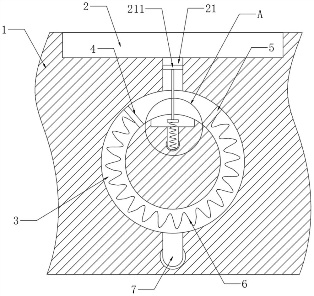
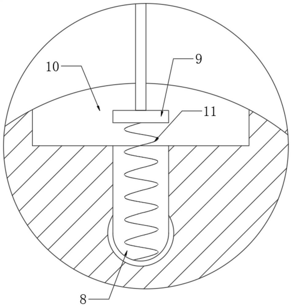
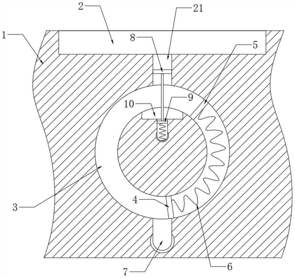
[0023] refer to Figure 1-3 , a sponge city road drainage system, including a drainage channel 2 dug on the subgrade 1, an annular groove 3 is dug under the subgrade 1, and the annular groove 3 and the drainage channel 2 are connected through a diversion channel 21, and the annular groove 3 is slidingly connected with a first baffle 4, and the annular groove 3 is fixedly connected with a second baffle 5, and the first baffle 4 and the second baffle 5 are elastically connected by a first spring 6, and the guide groove 21 A filter screen 211 is embedded in it, an arc-shaped groove 10 is opened on the inner wall of the annular groove 3, a water supply pipe 7 communicating with the annular groove 3 is buried in the roadbed 1, and a sewage discharge pipe communicating with the arc-shaped groove 10 is also embedded in the roadbed 1 The pipe 8 and the arc groove 10 are slidingly connected with a sealing plug 9. It should be noted that after the sealing plug 9 enters the sewage pipe 8...
Embodiment 2
[0026] refer to Figure 4-6 , and the difference from Embodiment 1 is that a storage tank 12 is dug on the roadbed 1, and the storage tank 12 communicates with the diversion tank 21 through the first diversion tank 13, and a scraper is slidably connected in the first diversion tank 13 17. The inner wall of the diversion groove 21 is provided with a second flow diversion groove 14, and a pushing device for pushing the scraper 17 to move is installed in the second flow diversion groove 14.
[0027] The pushing device includes a third spring 15 fixedly connected to the inner wall of the second shunt 14, and the third spring 15 is fixedly connected to the scraper 17, the scraper 17 is made hollow, and an electromagnet 171 is installed in the scraper 17. An iron limiting block 16 is fixedly connected to the inner wall of a splitter groove 13 .
[0028] It should be noted that the iron limit block 16 is set at the notch position of the first splitter groove 13, on the one hand, it ...
PUM
 Abstract
Description
Claims
Application Information
 - R&D
- Intellectual Property
- Life Sciences
- Materials
- Tech Scout
- Unparalleled Data Quality
- Higher Quality Content
- 60% Fewer Hallucinations
Browse by: Latest US Patents, China's latest patents, Technical Efficacy Thesaurus, Application Domain, Technology Topic, Popular Technical Reports.
© 2025 PatSnap. All rights reserved.Legal|Privacy policy|Modern Slavery Act Transparency Statement|Sitemap|About US| Contact US: help@patsnap.com


