
Optical fiber preform rod tail wire drawing control system and method

An optical fiber preform and rod tail drawing technology, which is applied in photovoltaic modules, photovoltaic power generation, manufacturing tools, etc., can solve problems such as affecting the qualified rate of products, unqualified production parameters, and large diameter of optical fiber preforms.

Pending Publication Date: 2020-12-18
江苏南方光纤科技有限公司
View PDF5 Cites 3 Cited by
  • Summary
  • Abstract
  • Description
  • Claims
  • Application Information

AI Technical Summary

Problems solved by technology

[0002] In the existing optical fiber preform drawing process, due to the large diameter difference of the optical fiber preform, in order to ensure the qualified rate of the product, employees need to waste a lot of time on the uninterrupted adjustment of the drawing process. In order to ensure the stability of the cut-off wavelength, drawing speed and tension when the rod is drawn to the end of the rod, it is necessary to manually intervene the value of the rod feeding speed and furnace power frequently
[0003] These frequent manual intervention actions occupy most of the production staff's time watching the line. If the line watching staff changes during the line watching period, or needs to assist the production with other tasks such as hanging rods and changing paint, it will be very difficult during the monitoring blank period. Potential for out of specification production parameters, especially at the end of the club
This will reduce the consistency of the product, directly affect the pass rate of the product, increase the production cost in a disguised form, and increase the line-seeing pressure of the production line personnel

Method used


Image

  • Optical fiber preform rod tail wire drawing control system and method
  • Optical fiber preform rod tail wire drawing control system and method

Examples


Embodiment

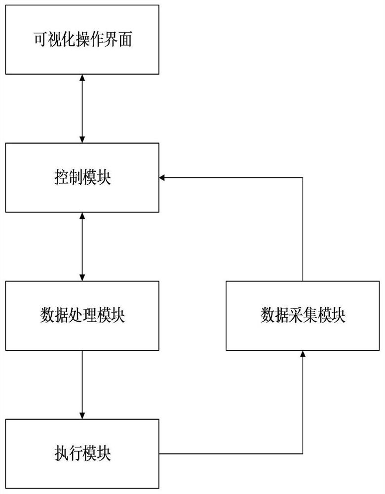
[0075] The invention discloses an optical fiber prefabricated rod tail drawing control system, which includes a visual operation interface for setting and viewing parameters connected in sequence, a control module for controlling the execution module to draw according to the control parameters, and a control module for controlling the parameters. A data processing module for adjustment and an execution module capable of wire drawing, and a data acquisition module capable of collecting optical fiber specification parameters and production line status in real time and transmitting them to the control module is connected in communication between the execution module and the control module. With the above optimized design, during the wire drawing process, all parameters are visualized, which is convenient for personnel to check; the degree of automation is high, which reduces manual participation and improves product consistency.

[0076] Specifically, the parameters to be set and ...


PUM


Abstract

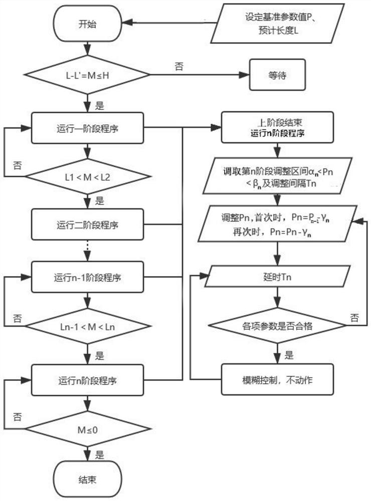
The invention discloses an optical fiber preform rod tail wire drawing control system and an optical fiber preform rod tail wire drawing control method. The system comprises a visual operation interface, a control module used for controlling an execution module to carry out wire drawing according to control parameters, a data processing module used for adjusting the control parameters and the execution module capable of carrying out wire drawing; the visual operation interface, the control module, the data processing module and the execution module are in communication connection in sequence,and a data acquisition module capable of acquiring optical fiber specification parameters and production line states in real time is in communication connection between the execution module and the control module. The method comprises the steps that firstly, the control parameters of different stages are set, and the specification parameters obtained after wire drawing are monitored; after an optical fiber preform enters a rod tail, the optical fiber preform is subdivided into n stages, the control parameters of each stage are independently set, and the control parameters are finely adjusted by taking specific time as an interval, so that the specification parameters are kept constant until the optical fiber preform is completely drawn. According to the device, the automatic procedure of rod tail wire drawing is greatly improved, the manual participation degree is reduced, the product consistency is ensured, the cost is low, and the efficiency is high.

Description

technical field [0001] The present invention relates to the technical field of intelligent control systems and methods, in particular to a control system and method for rod tail drawing of an optical fiber preform. Background technique [0002] In the existing optical fiber preform drawing process, due to the large diameter difference of the optical fiber preform, in order to ensure the qualified rate of the product, employees need to waste a lot of time on the uninterrupted adjustment of the drawing process. In order to ensure the stability of the cut-off wavelength, drawing speed and tension when the rod is drawn to the end of the rod, it is necessary to manually intervene the value of the rod feeding speed and furnace power frequently. [0003] These frequent manual intervention actions occupy most of the production staff's time watching the line. If the line watching staff changes during the line watching period, or needs to assist the production with other tasks such as...

Claims


Application Information

Patent Timeline
IPC IPC(8): C03B37/025H02S20/00
CPCC03B37/0253H02S20/00Y02E10/50
Inventor 施明杰黄均亮刘振华宗营卜惠华章强李松良
Owner 江苏南方光纤科技有限公司
Learn More